In this article, we’ll cover how to design a part that successfully leverages our countersinking capabilities for your design. To show how you can save time on post-laser operations, we’ll also bend and powder coat the part so it arrives ready to install, right out of that shrink-wrapped packaging.
You can make just about anything with a flat piece of metal cut in the right shape; in fact, that’s our business model! Just about. Add bending, tapping, powder coating, hardware, and now, countersinking! All of a sudden the design possibilities are endless.
Counter + Sink = …?
While the etymology might get you thinking about kitchen or bathroom staples, countersinking is a fantastic way to get fasteners out of a sightline, conserve space, or remove an interference as two parts slide across one another. In this article, we’ll cover how to design a part that successfully leverages our countersinking capabilities for your design. To show how you can save time on post-laser cutting (not all materials we countersink are cut on the laser) operations, we’ll also bend and powder coat the part so it arrives ready to sell or install, right out of that shrink-wrapped packaging.
Kickstart Your Part
To begin, fire up your favorite CAD software and open the sheet metal part. In this case we’ll use SolidWorks. If you don’t have access to a commercial CAD package, Autodesk Fusion has a hobbyist license, or QCAD is an excellent free 2D alternative. For more information on our recommendations check out this article.
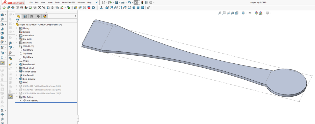
Fig. 1: The bounding box and bend lines indicate this is a sheet metal part flattened for DXF export.
With the outline drawn, the most reliable way to lay out your holes for countersinking is to model the part as it’s going to be used and add it to the assembly so any interferences can be addressed and the design can be refined.
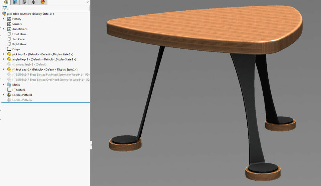
Fig. 2: Putting together the whole assembly helps optimize countersink placement.
In this case, we need to add holes for fasteners to attach the laser cut, bent and powder coated legs to the top of this end table and to the foot pads. With everything drawn to 1:1 scale, we can select fastener placement that complements the design, and more importantly, puts the holes where they won’t interfere with the bend lines or structural integrity of the part.
Choosing Material, Countersink Size, and Angle
For this build, 0.25” thick 5052 aluminum is being used because it is economical, lightweight and features like bending and countersinking are no problem. Imperial/SAE fasteners will be used since all other dimensions are in inches, which specifies an 82 degree angle for the countersink geometry. Critical design specifications for each material and thickness can be found on their respective material info pages under Design Considerations
The specific Design Consideration we need to factor in for our hole location is the “Countersink Min Hole Center to Material Edge” which is 0.781” for 5052 aluminum. Using the Hole Wizard in SolidWorks to lay out our hole pattern allows us to easily visualize the final geometry, including the major and minor diameter. We will set the holes 0.781” from the outside edge to stay within the guidelines.
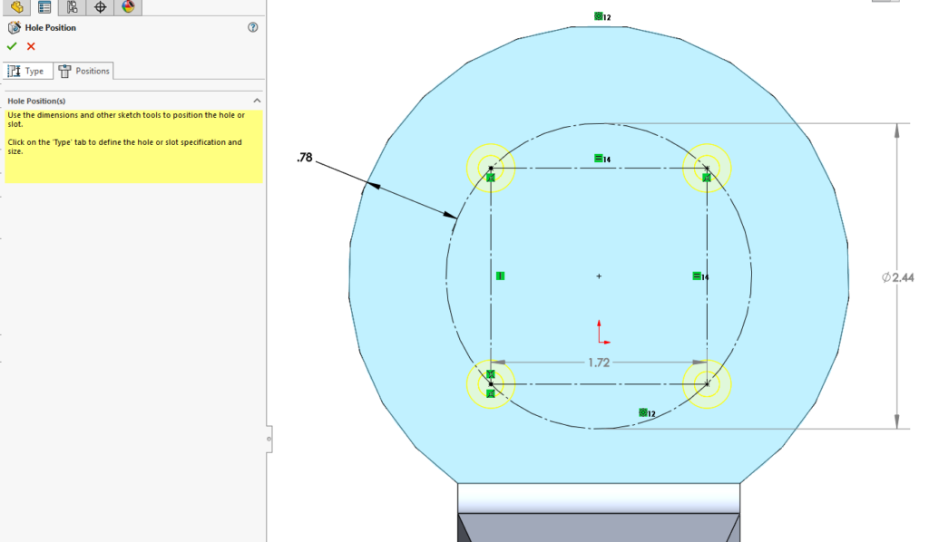
Fig. 3: The countersunk hole centers are set to stay away from the edges and bends in the material.
While planning your design, you’ll want to make sure the majors of your countersinks are outside of the die width that will be used to bend your part, since parts are countersunk before they’re bent at SendCutSend. Cut features that fall within the die of our tooling will be distorted.
You can find the full die width for the material thickness of your choice on the material info page. Simply divide the die width by 2 and measure that distance from the center of your bend. Make sure the edge of the major of any countersunk hole is at least that far away from the center of any bends. We have more information about planning features around bends here.
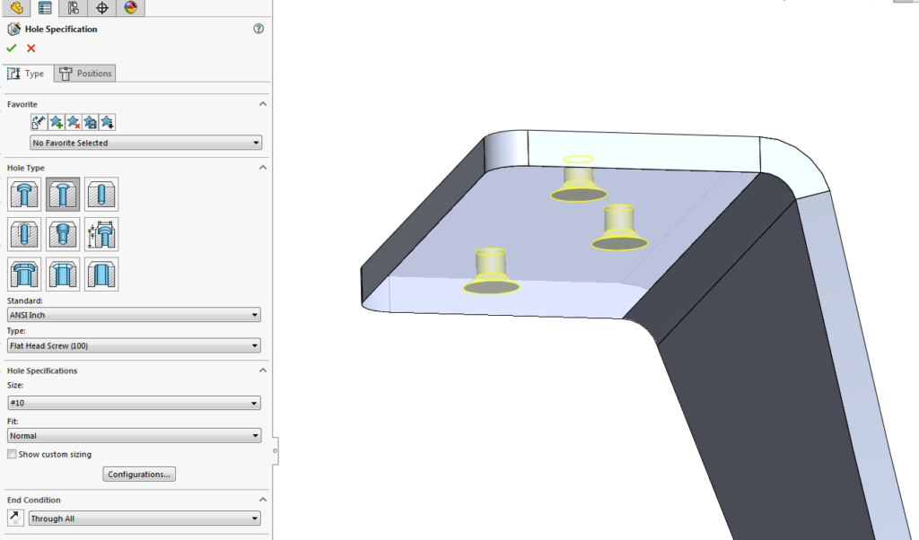
Fig. 4: The Hole Wizard also allows us to select the type of countersink, angle, and diameter.
The holes that allow the leg to be fastened to the top of the table need the countersink on the bottom face of the part, opposite the first pattern. For both hole patterns, a SAE #10 size hole has been selected, which falls within the specifications for 5052 aluminum and is a standard offered within the countersinking design guidelines.
The last thing to check before exporting is that our choice of fasteners mates well with the countersink geometry. McMaster Carr’s fastener library has an extensive list of specifications and drawings that can be imported into your CAD software to make this process a snap.
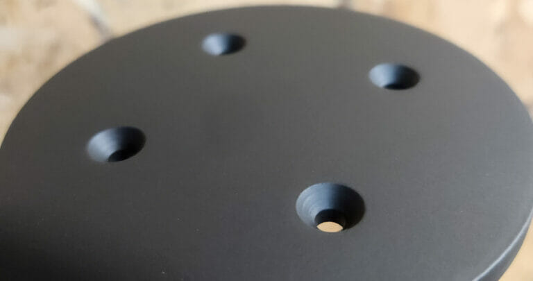
Here, a brass oval head #10 wood screw is used to contrast with the black powder coat on the part. From the product page for the fastener, we can see that the head diameter is 0.385” which will fit nicely in the 0.411” countersink we offer. See the countersinking design guidelines for a comprehensive list of the sizes available in Imperial and Metric standards.
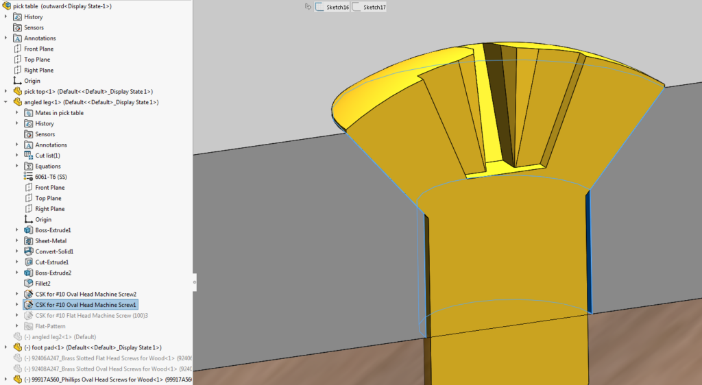
Fig. 5: The 82° angle and depth match our fastener well, and there is clearance on the minor diameter to prevent the screw from binding.
File Setup for Export
Now that the geometry is validated, you can save the part as a DXF and upload it to the website for instant pricing. If you’re using something other than CAD software, check out our guidelines to make sure you’re uploading the correct file type. Guidelines for setting up your file for bending can be found here.
Remember that specifying which holes to countersink, and on which face to do it, is done within the online configurator, so be sure to remove the outer circumference (major diameter) if it’s shown on the DXF.
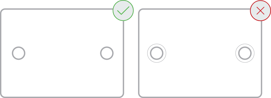
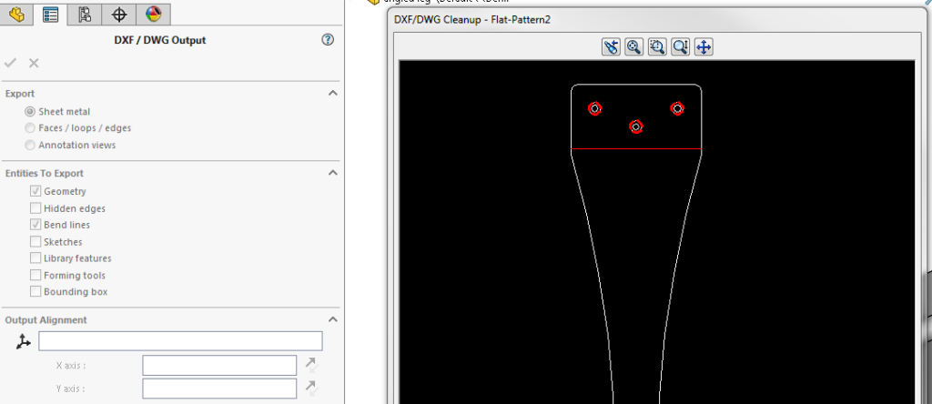
Fig. 6: Remove the major diameter line entities (highlighted red circles) before saving.
Ordering Parts with Countersunk Holes
With the part exported as a DXF, a drag-and-drop operation is all it takes to upload it to our website. Once you choose a material you can choose to add hole operations. Now, select “countersinking” and click the drop-down arrow circled in the figure below to specify which operations for each individual hole.
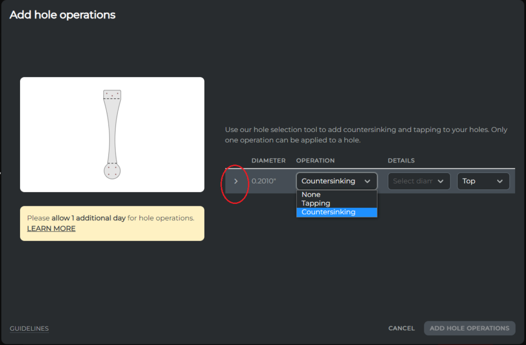
Fig. 7: You can choose the operations you want to add to each hole individually.
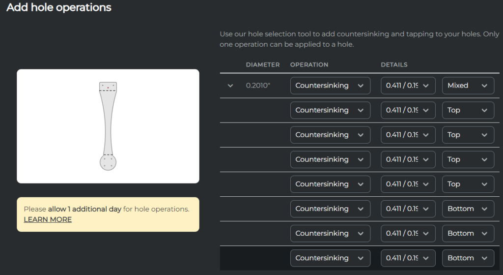
Fig. 8: The final selections for our example part.
As you select each available hole, you will see it highlighted on the part preview. It’s just a matter of confirming which diameter and on which face to countersink.
Add any other operations now, in our case, we’ll add powdercoating and bending (deburring is automatically selected if applicable.)
Your part is now ready to review and order. Note that some operations will add a few days to the lead time of your part. We are always working to minimize this time to get your parts out the door and into your hands as fast as possible.
Get your files uploaded and see an instant pricing today!


