In today’s world, there is a high demand for parts that are lightweight, strong, and cost-effective. Although general intuition may yield a promising solution, is this truly possible with design optimization in CAD? Is the design really the best it can be? Could the part be lighter, stronger, or made from a better material? With so many factors to consider, the process can quickly become overwhelming.
Fortunately, it doesn’t have to be!
By using optimization tools in 3D modeling software, this process can be automated to find the best solutions.
This article will lay the groundwork for understanding optimization problems, demonstrate how to use CAD for optimizing a part, and assess whether the results are worth the extra analysis.
What is a Design Optimization Problem?
To put it simply, an optimization problem is all about finding the best way to meet a set of goals and requirements. Here’s a breakdown of the key components:
The Objective
An optimization study starts with a clear goal. Without a defined objective, the algorithm doesn’t have any directions. Common goals might include reducing mass by 10%, increasing the factor of safety to 2.0, or limiting deflection to 0.001 inches. Depending on the requirements for the part, it is up to the designer to specify the exact need.
Decision Variables
With the objectives in place, the next building block of an optimization problem is decision variables. These variables tell the algorithm what aspects of the design it can adjust. For instance, while it may be desirable to maintain the thickness of a part, the overall width could change. Or perhaps the size of a hole can be modified, but its position needs to remain fixed. Defining these variables ensures critical design features are preserved.
Constraints
Constraints establish the boundaries and limits of the design space. They let the algorithm know what the expectations are for an acceptable solution. A few examples of constraints could be the upper and lower boundaries of a decision variable, the maximum allowable stress, or even manufacturing constraints.
Constraints can be equality-based (e.g., x = 5) or inequality-based (e.g., x < 5). Clearly, inequality constraints will offer a broader search space, while equality constraints require a specific value to be met.
Methods
Parametric Optimization involves adjusting parameters within set limits to achieve a desired outcome. For example, if a hole is used to reduce weight, the hole’s diameter is varied within a specified range. A larger hole offers a larger weight benefit, but may compromise the overall strength of the part if it gets too big. A simulation is run for each diameter, and the best hole diameter is selected, depending on the goals and constraints. This method can either be performed manually or automated through CAD software.
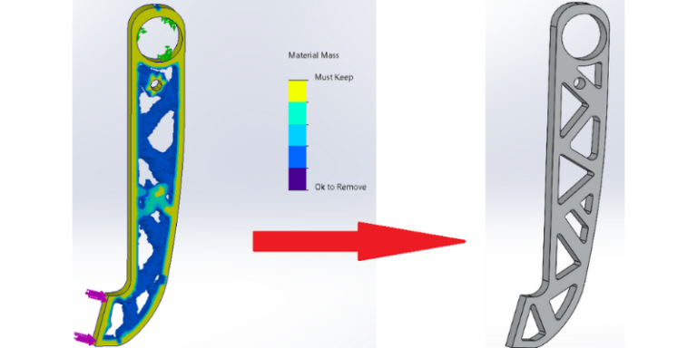
Topology Optimization differs from parametric by allowing modifications beyond existing features. It can introduce new structures, often resulting in organic and unconventional looking designs. Because these new structures may not align with the intended manufacturing strategy, the original part needs to be adjusted to match the optimized result. More details will be provided in the topology optimization example.
Machine Learning Optimization leverages existing data to inform future decisions. This approach can automate parts of the design process and predict performance without extensive simulations. While not covered in this article, machine learning optimization is worth considering for larger-scale projects.
Why is Optimization Useful?
- Reduce Weight
- Cut Costs
- Improve Performance
- Generate New Designs
- Minimize Material Waste
- Save Time
Example 1: Parametric Optimization in Solidworks
With a clear understanding of what an optimization problem is, the next step is to apply these concepts using CAD software to perform an optimization. In this example, a brake pedal is optimized parametrically using SolidWorks. While SolidWorks is used here, the same principles apply to other modeling software. Note: Setting up a static FEA simulation is a prerequisite for running these optimization examples and is not covered in depth in this article.
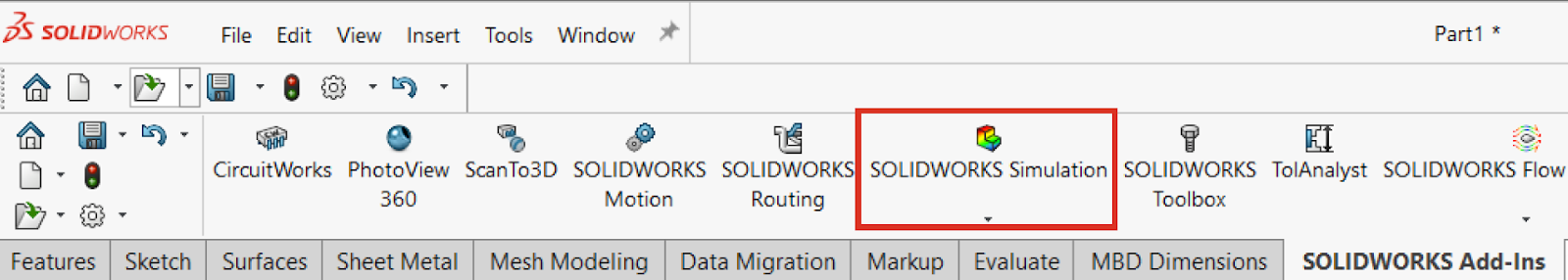
To get started, load SolidWorks Simulation from the add-ins tab.
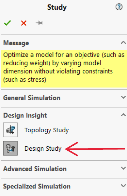
Select “New Study” and choose “Design Study” for parametric optimization. In example 2, “Topology Study” will be used. The “Design Study” option can also be found under the Evaluate tab.
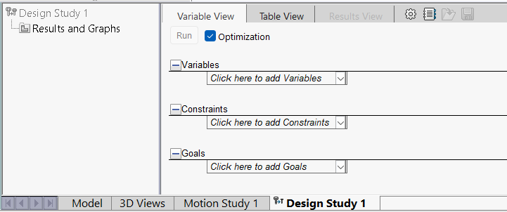
Once selected, a toolbar will appear on the bottom of the screen. Hopefully the information on this screen seems familiar, since it consists of variables, constraints, and goals, the framework of an optimization problem!
Variable Tab
After selecting the “Click here to add Variables” dropdown, a window will appear where the decision variables for the study can be specified.
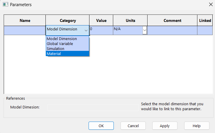
The variables can be categorized into four types: model dimensions, global variables, simulation parameters, or materials. Once a category is chosen, the user can define the specific parameter, including its name, units, and any additional comments. In this example, the material category is selected to compare different materials that could be used for manufacturing this part.
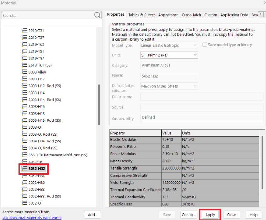
Material options and thicknesses are available on SendCutSend’s website: SendCutSend Materials. For this part, 6061 T6 aluminum, 5052 H32 aluminum, A36 mild steel, and 304 stainless steel are considered, as they can all be cut from a .500” thick plate required for this part.
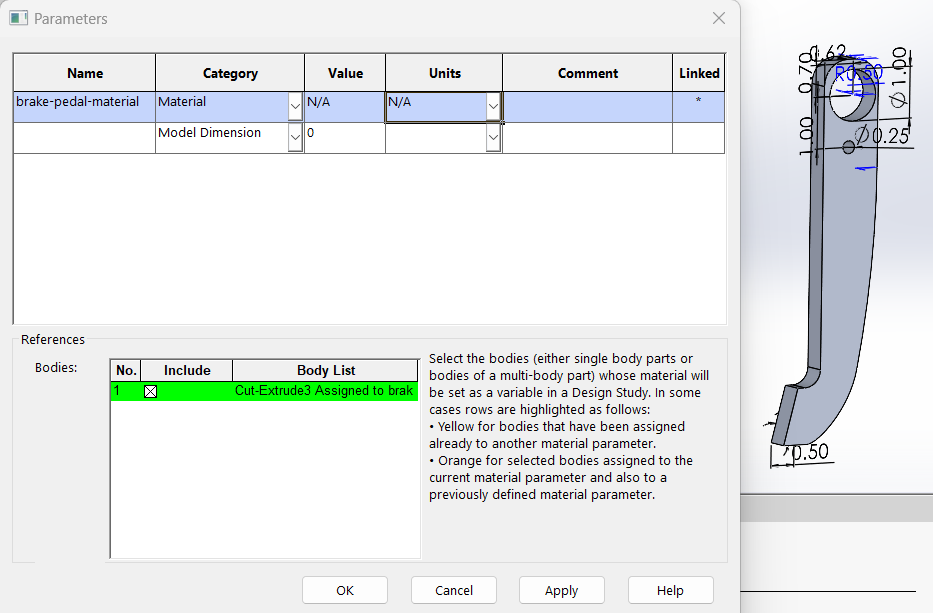
After selecting the materials of interest, they are added to the variable labeled “brake-pedal-material,” as illustrated in the figures below.
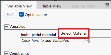
For simplicity, the only variable considered in this experiment is the material, but a user may specify up to 20 design variables!
Constraints Tab
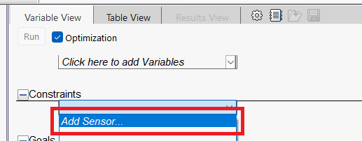
Next, set up the constraints in the Constraints tab. Select “Click here to add Constraints” from the design study menu and then choose “Add Sensor.” In this example, a mass sensor is added to constrain the maximum weight.
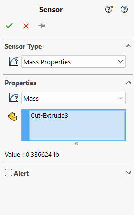
Additionally, a factor of safety constraint is included to ensure the part can withstand the force load from the static stress simulation.
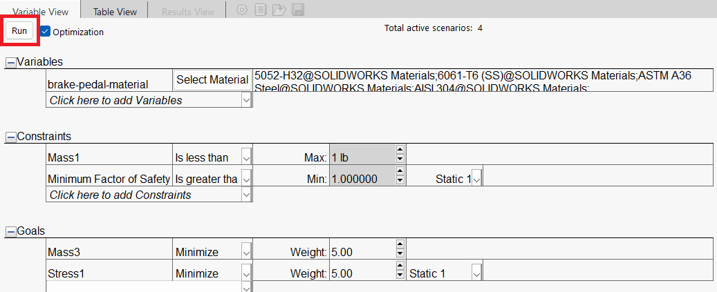
Once the sensors are added, more details will appear in the constraints tab of the main design study menu. Here, the constraint boundaries are defined: in this case setting the maximum mass to 1 pound, and the minimum factor of safety from the simulation to 1.0.
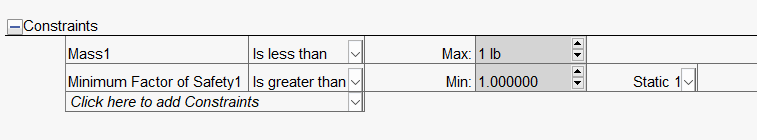
Although there are only two constraints in this example, a user can specify up to 60 criteria in a design study!
Goals Tab
The goals tab is where the rubber meets the road. Here, the design objectives are set to output the desired results. Depending on the study’s complexity, these goals may require several rounds of refinement to produce the most practical and realistic outcomes.
In the goals tab, a mass sensor and a stress sensor are added, similar to the process used for setting constraints. For clarity, this process is illustrated in the figures below.
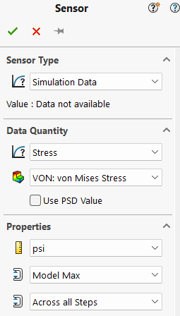
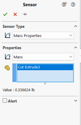
After adding the sensors, define the goals in the main window. In this example, two goals are set: minimize the mass and minimize the maximum stress. The weight of each goal can also be adjusted to prioritize their importance. In this case, both goals are given equal weight.
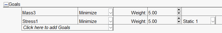
To achieve the best results, it is recommended to limit the number of goals to 3 or 4 during a study.
Run the Experiment
With the variables, constraints, and goals set, it’s time to run the optimization! At the top of the setup, the total number of active scenarios is displayed. Since this study evaluates four materials, there are four scenarios to process. While additional scenarios will extend the solve time, they also expand the search space for finding the optimal solution.
Drum roll please!
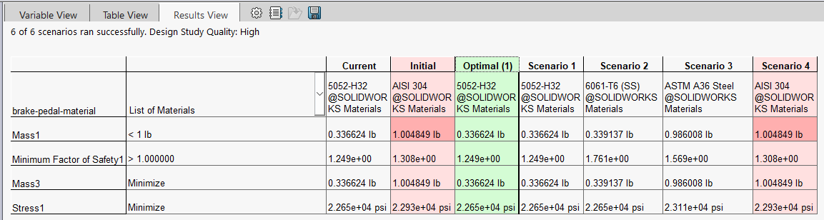
After running all four scenarios, the results are compiled into a table. In this case, the optimal material for meeting the constraints and goals is 5052-H32 aluminum, indicated in green. In contrast, 304 stainless steel is highlighted in red, as it exceeds the 1-pound mass constraint.
Just like that, SolidWorks has come up with an optimal SendCutSend material for this brake pedal to meet the design requirements!
Example 2: Topology Optimization in Solidworks
In this example, the same brake pedal will be optimized in Solidworks, instead this time using topology optimization rather than parametric optimization. Again, although Soldiworks is used in this case, the same framework can be applied to other modeling software.
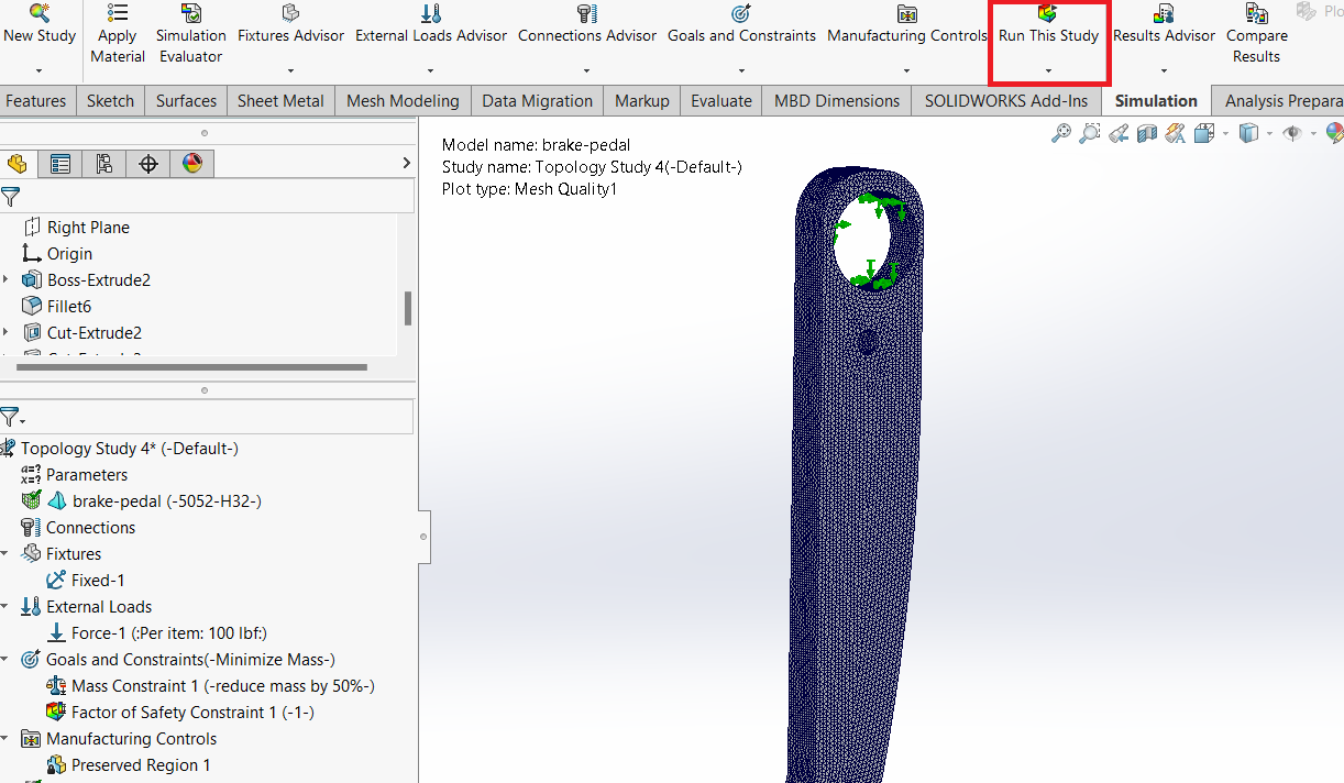
Instead of selecting “Design Study” as in example 1, choose “Topology Study,”. This will open the menu displayed below.
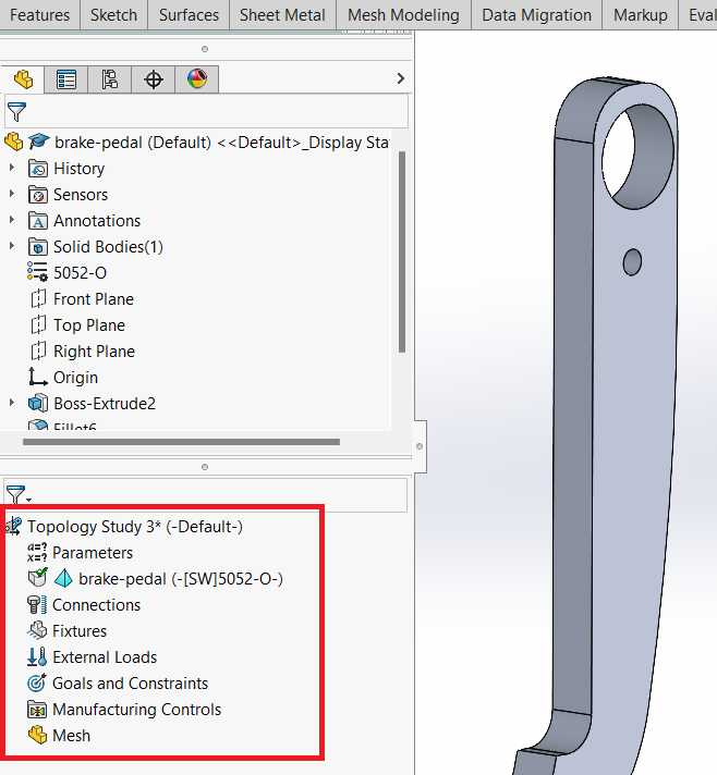
Parameters
As discussed in the previous example, parameters can include model dimensions, global variables, simulation parameters, or material properties. These parameters can be easily accessed and modified by right-clicking on this category.
Connections
A connection defines how different features of the design interact with their environment. Connections can be used to simplify an assembly by replacing entire parts with the right connector. Examples of connections include springs, welds, or bolts. In this simulation, no connections are used.
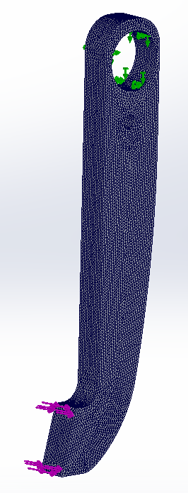
Fixtures
Fixtures determine how a part is secured. They can prevent motion entirely or allow for a specific displacement. In this case, a fixed support is applied where the brake pedal is bolted. Details on fixtures will be covered in future FEA articles.
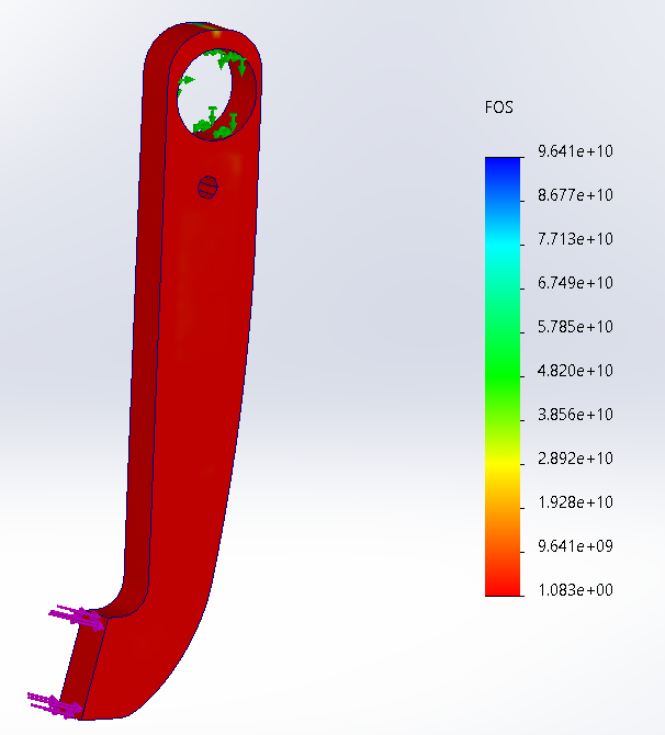
External Loads
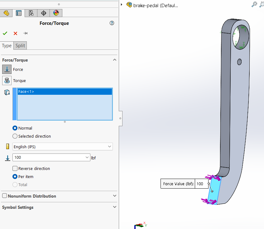
External loads simulate the forces encountered in the part’s environment. These loads can come in many different forms, but in the brake pedal case, a force load is applied to simulate a driver pressing on the brake pedal. This load is shown in the figure to the right. Loads shall also be covered in additional detail in FEA articles.
Goals and Constraints
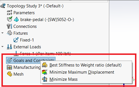
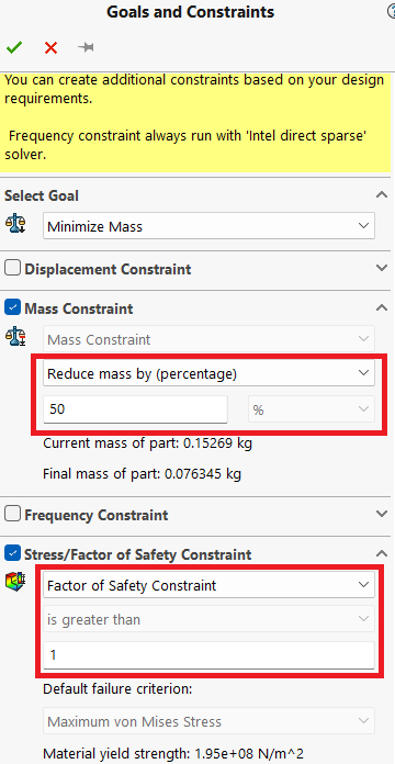
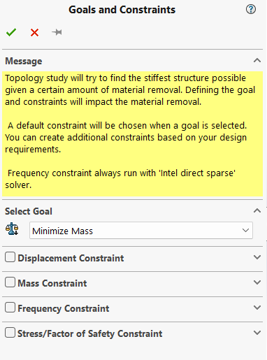
By now, this section should feel very familiar. By right-clicking on this category, users can define one of the three goals shown. Unlike parametric optimization, only one goal can be selected at a time in this optimization strategy. In this experiment, the goal is to minimize the mass of the brake pedal, essential for a lightweight part in a performance race car.
Once the goal is set, constraints can be applied. As illustrated in the window below, constraints can include displacement, mass, frequency, or stress/factor of safety. For the brake pedal, a mass constraint is added to reduce the mass by a specific percentage, and a factor of safety constraint ensures the part will not fail under the simulation forces.
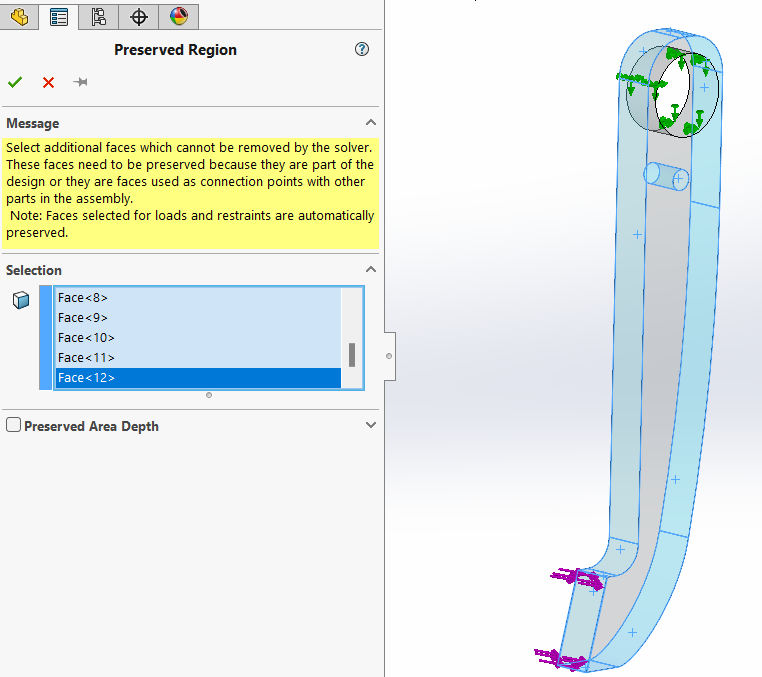
Manufacturing Controls
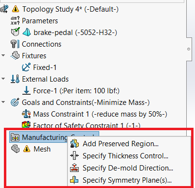
Manufacturing controls allow a user to set restrictions on what material may be removed. The four manufacturing controls include preserving specific regions, specifying thicknesses of the resultant structures, de-mold direction, or planes of symmetry. For the brake pedal, a preserved region is added to maintain the outer shape and the diameter of a hole feature.
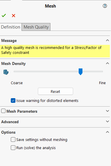
Mesh
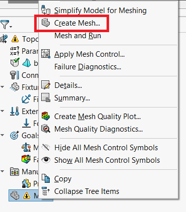
Meshing a part involves dividing the entire geometry into smaller pieces for finite element analysis. Each piece is calculated individually rather than using a complex mathematical model to simulate the entire part at once. Meshes come in many shapes and sizes and building them correctly is crucial for accurate FEA results. In this example however, a very rudimentary mesh is created. The user can adjust how coarse or fine the mesh is. A finer mesh will increase the solve time for the simulation, but will yield more continuous results.
Results
The topology optimization is ready to go with a goal to reduce the mass by 40%! Click “Run This Study” to perform this optimization.
Note: Depending on the complexity of the model and setup, the solving process may take some time.
Fortunately, the results are only one scroll away!
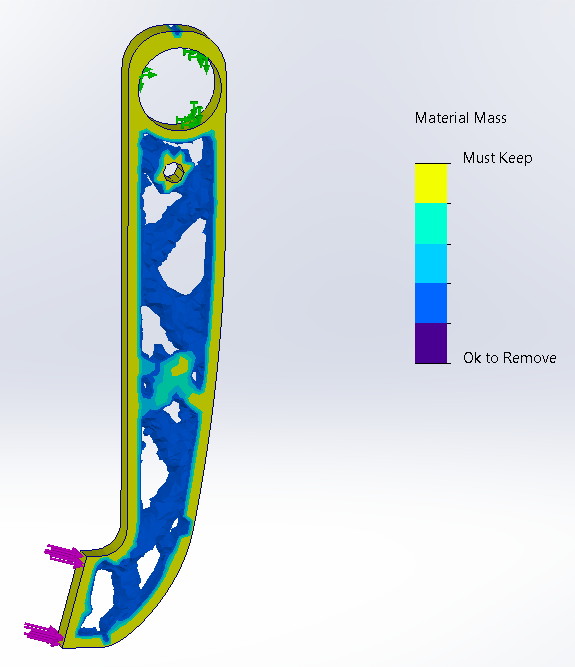
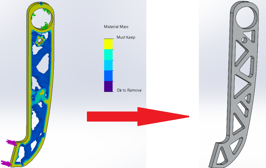
At last, a successful topology optimization has been executed for this brake pedal. The first output of the study is the material mass plot, shown above. This indicates the final material distribution from the last iteration of the optimization.
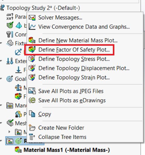
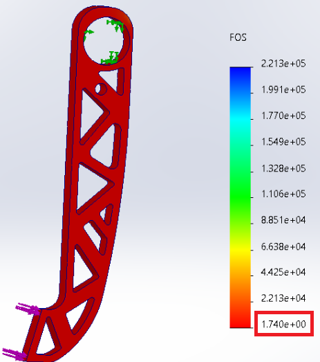
By right clicking on the results tab, additional plots can be defined and analyzed for this new geometry. For this example, a factor of safety plot is defined, to verify that the solution meets the minimum factor of safety criteria of 1.
Great news! With the optimized geometry, the part can still withstand the braking force.
Converting the Results
One of the downsides to topology optimization is that it can create structures that are not manufacturable. However, it does provide an indication of where mass may not be needed. These regions need to be manually modeled back into the original part. Below is an example of how the results from the optimization study are translated back into geometry that can be cut on a flat plate.
After the results are converted, make sure to re-run any simulations or calculations to ensure that the part still meets all of the requirements.
Design Optimization in Cad Is It Worth It? SendCutSend Comparison
In example 1, the material for the brake pedal was optimized. The table below displays the cost associated with cutting the brake pedal from each material.
Parametric Optimization: Results
| Material | Parametric Material Optimization |
| 5052 H32 | $16.20* |
| 6061 T6 | $18.80 |
| 304 SS | $29.85 |
| A36 | $18.81 |
* SendCutSend price is only used as an example and is subject to change at any time.
This example highlights the advantages of design optimization in CAD. In using an optimization approach, the best material to meet the goals and requirements also turned out to be the most cost-effective! While this won’t always be the case, selecting the right material can lead to significant long-term savings.
Topology Optimization: Results
Once 5052 H32 aluminum was selected as the material, a topology optimization was carried out in example 2 with the goal of reducing the weight by 40%. All said and done, the brake pedal’s weight was reduced by 37%!
| Non-Optimized Part | Optimized Part | |
| Weight | .34 lb | .21 lb |
| Cost | $16.20 | $33.70 |
However, lightweight, high-performance custom parts typically come with higher costs, reflected in the table above. This is why it is so important to identify the right goals and requirements for the part to justify any additional expenses.
And there it is—design optimization in CAD isn’t just about finding a solution; it’s about finding the best solution. By leveraging parametric and topology optimization, designers can go beyond intuition and automate the search for the best outcomes. Whether it’s reducing weight, cutting costs, or enhancing performance, there’s always room for improvement. So, next time you’re designing that critical part, remember: don’t guess—optimize!
This article was guest submitted by Alexsander Hurwoth, a SendCutSend customer.


