
From concept to finished product, sheet metal bending requires a deliberate, thought-out design and intentional manufacturing. There are a few major steps to successful bending:
1: Initial Design
2: Preparing Your File
3: The Bending Process
4: Finishing Processes
We have a variety of helpful resources on bending, but let’s walk through these key steps so you can achieve the best results from SendCutSend.
Basic Sheet Metal Bending Terms
Before we jump into our step-by-step guide, there are a few basic bending terms that you should know. The video below goes through all those definitions and will help you prepare for creating a successful bent sheet metal product.
Step 1: Initial Design Prep for Sheet Metal Bending
We’re going to go over some general design principles for bending, but be sure to check out our software tutorials to see specific examples.
Use SendCutSend’s bending radius + K factor
Bending specifications like bend radius and K factor are set per material thickness and we do not offer custom bend radii at this time.
Be sure to design using our material bending specifications so your parts turn out as expected! You can confirm bending specifications in our Material Catalog or Bending Calculator.
- Using Autodesk Fusion or SolidWorks? Download our gauge tables to apply the latest specifications with a few clicks.
Bend deduction calculations for sheet metal
One of the most important things to take into consideration when designing bent sheet metal is bend deduction. Bend deduction accounts for the “stretching” that happens in a material when it is bent. Bend deduction changes based on the material, thickness, and angle of the bend being created, but essentially it’s making your part slightly smaller to make room for the stretched material around the bend.
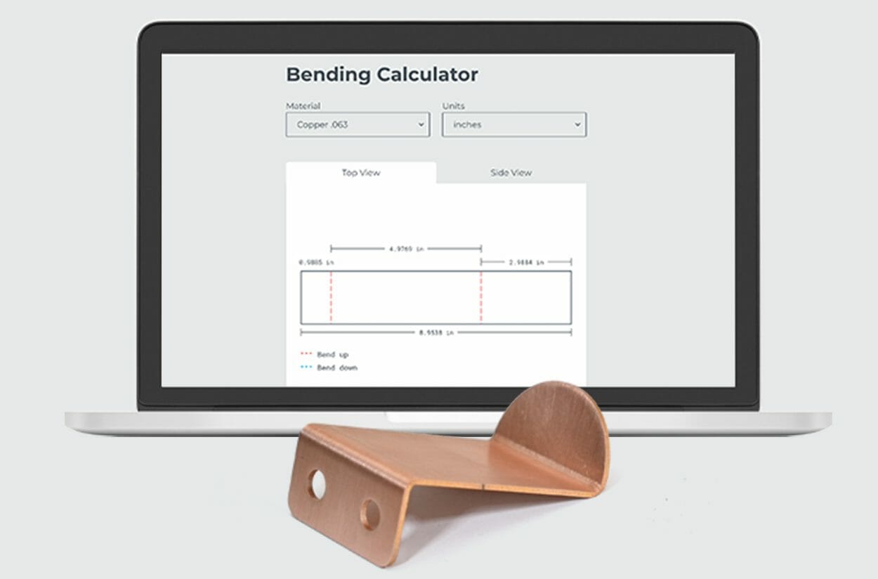
The best way to see what dimensions you should be using on your bent parts is to use our online bending calculator. Our bending calculator is especially useful if you’re designing in a 2D program like AutoCAD, QCAD, or Adobe Illustrator.
If you design in a 3D CAD program, setting up sheet metal rules using our bending specifications mentioned above is typically the easiest way to ensure bend deduction is calculated in your software.
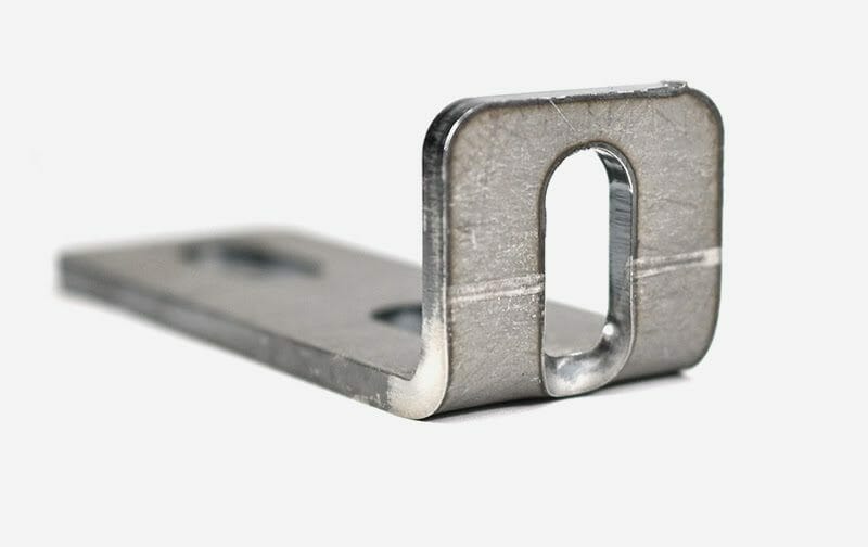
Flange length
You will also need to know what flange length you’ll need and if that length will work in your chosen material. (The flange is the edge of the part that’s bent from the stationary base.) For sheet metal bending with SendCutSend, the minimum flange length varies by material and thickness.

To see the full list of minimums and maximums for SendCutSend’s bending service, check out our Bending Min/Max Chart.
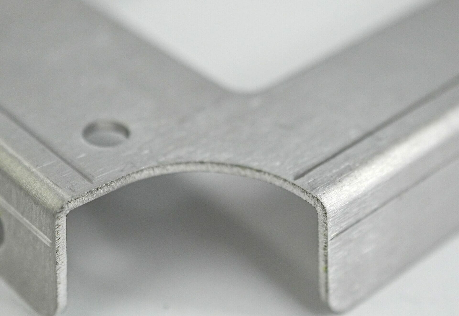
Bend relief notches for sheet metal parts
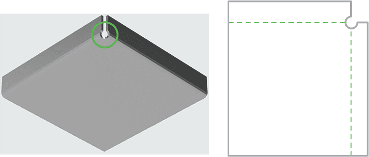
To reduce bulging in the corners of your bent parts and prevent tearing, you can incorporate bend relief notches into your design. Bend relief notches are just narrow notches or circles put into the corners of your design. These notches should be at least 50% of the material’s thickness in width and the depth should equal Bend radius + Material thickness +.020”. These notches allow for less stress on the inner radii of the flanges, and will help keep the corners of the bends from interfering with the base material.
Features spaced away from die line
Adequately space all holes and features away from the die line. Each material and thickness has its own recommended distance between features and the die line. See our guide to avoiding deformation and reference the specifications for your chosen material to make sure your bent part will not experience any feature warping.
Step 2: Preparing Your File for Successful Sheet Metal Bending
If you plan to upload a 2D file, save or export your file in one of these vector formats: DXF, DWG, EPS, or AI (Adobe Illustrator). If you will upload a 3D file, save your design as a STEP or STP format file and ensure it meets our 3D File Guidelines.
How to create bend line indicators in CAD programs
If you’ll be uploading a 2D vector file, make sure that you are using the correct lines to indicate bends. The bend line indicator we prefer changes depending on what program you are using to design your parts, and we’ve laid it all out in this chart:
| SOFTWARE | 3D FORMAT | 2D FORMAT | BEND LINE (2D formats only) |
| Fusion | .step, .stp | .dxf | Solid line (default) |
| SolidWorks | .step, .stp | .dxf | Dashed centerline (not Hidden)* |
| AutoCAD | .step, .stp | .dxf | Dashed line |
| OnShape | .step, .stp | .dxf | Dashed line |
| Adobe Illustrator | N/A | .ai | Solid, separate color from cut lines |
| Inkscape | N/A | .eps | Solid, separate color from cut lines |
| CorelDraw | N/A | .eps | Solid, separate color from cut lines |
*SolidWorks may default to the Hidden line style which will not be detected by our system. Please be sure to use a different dashed line style.
While we accept .AI and .EPS files, it’s critical that your bend lines are parallel when uploaded from these software or the file will delay processing.
If you design your parts in Adobe Illustrator, please send us the original (native) ai file. We’ll take care of the conversion on our end. For the fastest turnaround on your order, we recommend designing your parts in a CAD software.
Pre-flight file checklist before parts can be built
Finally, make sure to follow our pre-flight checklist for file preparation and you’ll be ready to go:
- File is in a format that we accept (2D: .dxf, .dwg, .ai, .eps; 3D: .step or .stp)
- All holes and cutouts are at least 50% material thickness and adequately spaced away from the die line
- Bends set up correctly for the software and format
- File built at 1:1 scale, preferably in inch-units
- All objects are on the same layer
- No stray points, duplicate lines, empty objects, or text areas
- No shapes have open contours
- All shapes united, combined or merged
- Any text to be cut out has been converted to outlines or paths
- Cut-out text “stencilized” with bridges
Step 3: How The Sheet Metal Bending Process Works
Sheet metal bending is capable of forming many difficult parts and products, but tooling does have its limitations. There are a few bends that we don’t currently offer:
- No acute angles greater than 130°
- No curl, bump, or roll forming
- No coining
- No hemming

Each material and thickness we bend has a set bend radius. See our bending calculator to confirm the bend radius for the material you need.
Check out our full bending guidelines to see all the capabilities and limitations of CNC bending.
Bending will also add a little bit of time to your order, so check out SendCutSend’s processing and shipping policies. The estimated ship date for your order shows at checkout.
Step 4: Finishing Bent Sheet Metal
Bending may leave die marks on your parts, but these marks are purely cosmetic and will not affect your part in any way. While we don’t offer any protection to prevent die marks, they’re easy to remove with a DA orbital sander after you receive your parts.
You can also powder coat bent sheet metal parts, and it’s simple to add powder coating to your SendCutSend order. It’s important to note die marks can show through the powder coating, so while it won’t completely cover up machining imperfections, powder coating will give your parts a protective and aesthetic finish.
Making Sheet Metal Bending Simple
Our goal here at SendCutSend is to make bending a simple, understandable process, and we are continually growing our resource library to make that reality. Take a look at our bending FAQs and reach out to our support team with any additional questions.
After you have finished your design and prepared your file, upload it to our instant pricing tool and get your custom bent sheet metal project started!


