With the evolution of digital manufacturing, all you need to make high-quality custom parts is a computer and an idea; SendCutSend can take care of the rest.
Parts manufactured in the real world will inevitably have slight variations from the ideal CAD model. There is nothing worse than spending time and money designing a part, only to find that it does not work as intended in real life.
This article will cover what causes these variations, how to plan for them when designing to avoid issues with the final fitment of parts, and how to take advantage of the precision of these machines to create self-fixturing parts.
Common Terms and Definitions for Designing for Manufacture
These are a few terms that need to be understood when designing for manufacture:
Nominal – Ideal or theoretical value that may not match the real-life value. This explains the dimensions a part was designed to in a CAD program, the nominal dimension for the flange in Figure 1 is 4.625”
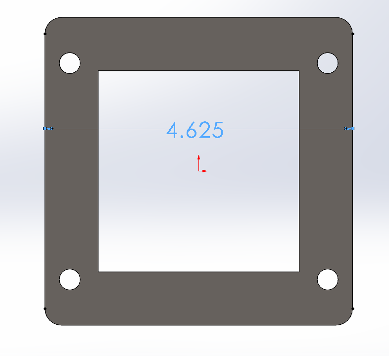
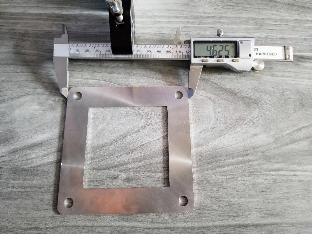
Accuracy – Describes how well something compares to a nominal value. This is something that can be easily measured on a finished part by comparing it to a calibrated caliper or other measuring device. The flange in Figure 2 was designed to be a 4.625” square nominally, the actual measured value is 4.625”. This shows us that the machine that cut this part is extremely accurate. It would require a more precise measuring technique to know exactly how accurate the machine is. The main takeaway is that modern Computer Numerical Controlled (CNC) machines are extremely accurate when properly calibrated and maintained.
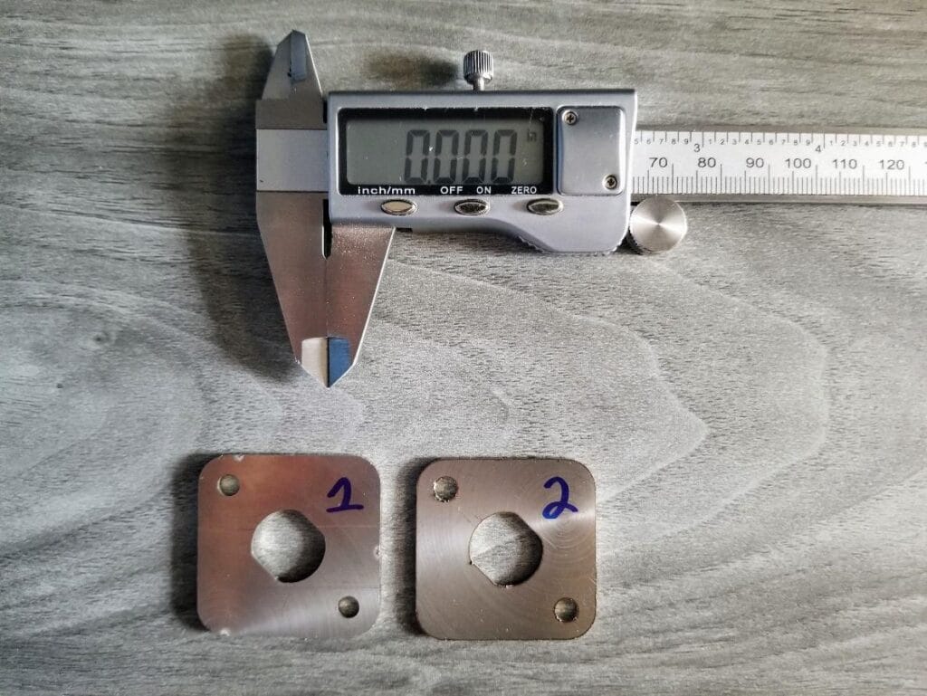
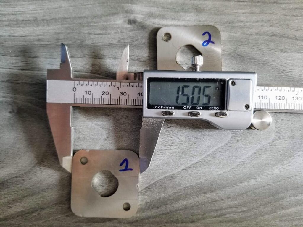
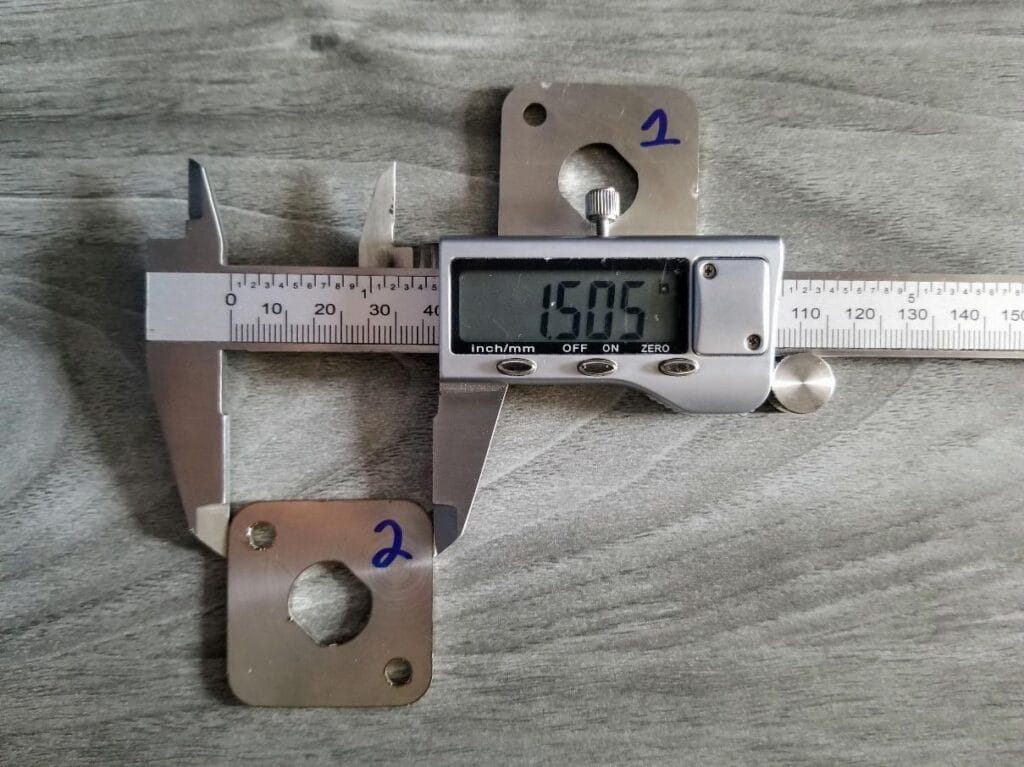
Precision – Describes how well something compares to previous iterations of itself. When talking about fabricated parts, this describes the repeatability of the manufacturing process from part to part. The parts in Figure 3 were designed to be 1.5” squares and were cut on the same machine. Figures 4 and 5 show the parts were made with such a high level of precision that you cannot measure the difference between the two with calipers. These parts are very precise but not as accurate as the flange from Figure 2 since they differ from the nominal 1.5” value by 0.005”.
Tolerance – Acceptable or expected variation in each part relative to a perfect part or nominal value. Considers both accuracy and precision in a single number. This value varies for different manufacturing methods and allows designers to ensure their parts will fit together despite expected variations from manufacturing. Good suppliers will advertise their machine tolerance in a +/- format so that designers can plan accordingly. Tolerance is a very important concept in manufacturing, CAD programs show a virtually perfect representation of a part and do not show the expected variations from manufacturing.
SendCutSend Tolerances:
SendCutSend offers many different services, each service will have a unique tolerance due to how the various machines operate. This article focuses on laser cutting and bending, but these concepts will apply to any other manufacturing service as well.
SendCutSend Laser Cutting Services
CNC laser technology has rapidly advanced in the last decade and has quickly become one of the most precise and cost-effective methods of cutting flat parts. These machines use a high-powered laser and an inert shielding gas to remove material in a controlled manner. The laser beam melts a small portion of the material while the shielding gas blasts the melted material away while also eliminating any oxides that may form due to the extreme heat. This process minimized the heat-affected zone and results in an extremely accurate and repeatable cut. It is also faster than many other CNC cutting methods.
- CNC Laser cutting tolerances
- +/- 0.005” over the entire part
- This means a 1.5” part can measure between 1.505” and 1.495″ and still be within the expected tolerance of the machine.
- Very small tolerance, standard printer paper is 0.004” thick!
- Larger parts are prone to more variation, this is considered when specifying machine tolerances.
- +/-0.01” Tab and slot tolerance – The tolerance doubles due to the stacking tolerance of two parts. If each part can be allowed +/- 0.005” of variation, both parts together can allow up to 0.005” x 2 = 0.01” of variation.
- Prone to less variation since material is being removed as the laser cuts.
- Warping is a possibility depending on part size and the amount of material removed due to heat input and residual stresses in the material.
- +/- 0.005” over the entire part
The parts shown in the examples above are all within the expected tolerance. Figure 2 is well within the expected tolerances. Figures 4 and 5 are consistently on the upper edge of the expected tolerance and leave no room for minor variations that are expected in manufacturing. If the parts were 30” instead of 1.5”, they would most likely fall outside of the expected tolerance. These parts came from another supplier that is due for a machine calibration.
SendCutSend Sheet Metal Bending Services
CNC air bending machines use nominal punch and die sets and variable force to bend metal. Modern machines use CNC end stops to locate the bend line precisely and calculate the required bending force based on the tooling size, material type and thickness, bend line length, and desired bend angle. These machines are extremely accurate but are prone to more variation due to part size and the large number of variables in the operation.
- CNC air bending tolerances
- +/- 1 deg up to 24” bend line length.
- +/- 2 deg 24” to 44” bend line length. Additional bend line length increases tolerance because of an increased force required to bend to the desired angle.
- Prone to more variation since the material is being permanently deformed.
- Small variations are magnified as the part grows.
- More susceptible to material variations in thickness and irregularities due to reliefs or features in the bend zone.
- Overall part tolerance grows with multiple bends.
The channel shown in Figure 6 was designed to be 4.25” wide with 1.5” edge flanges. Figure 7 shows the bottom of the channel measures as expected. Figure 8 shows the top of the bottom varies from the top by around 0.04” due to minor variations in bend angle.
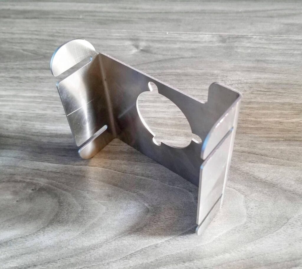
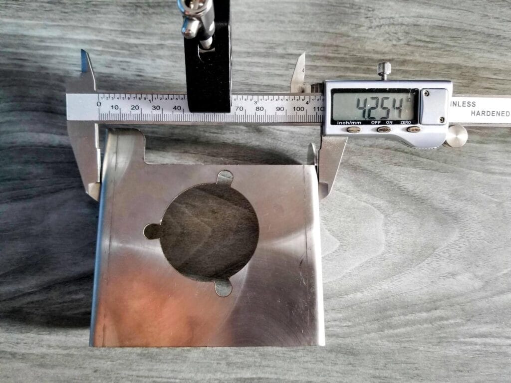
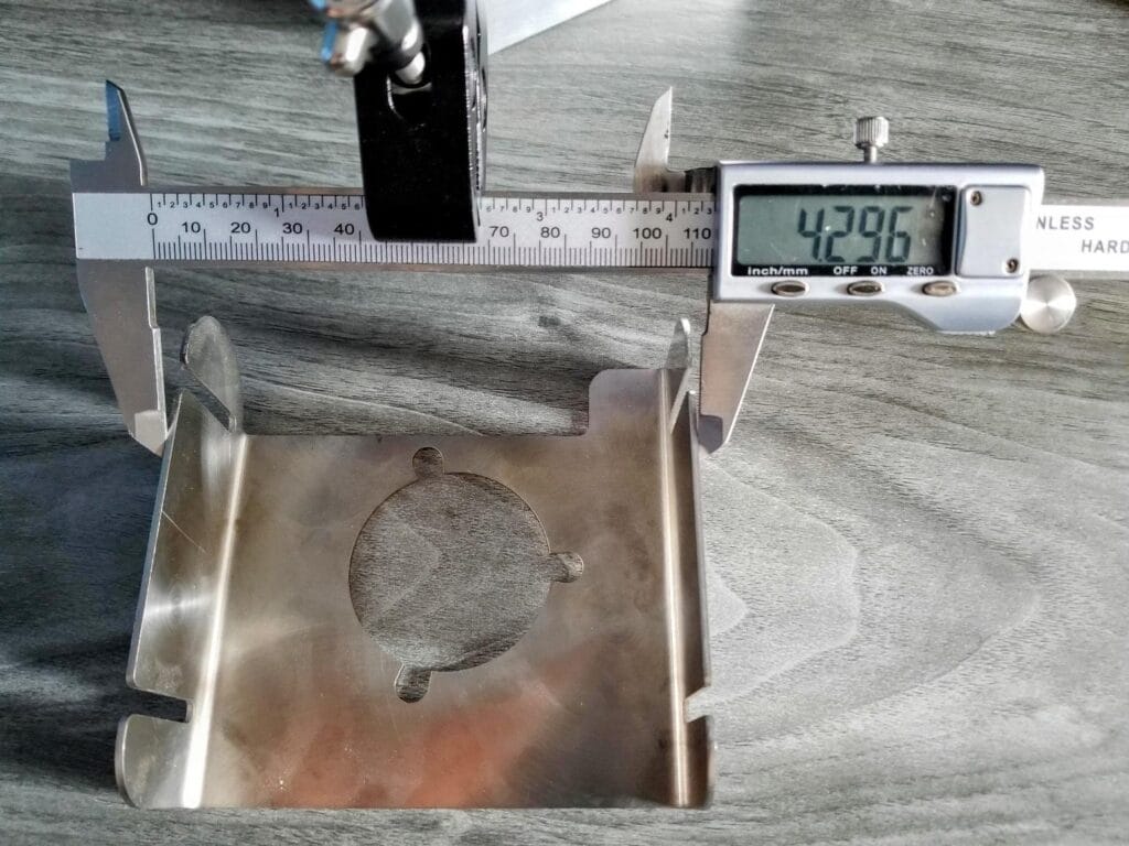
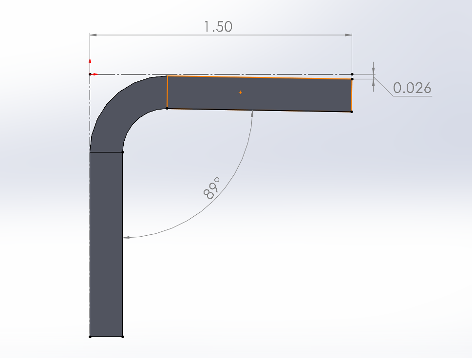
Figure 9 shows that a 1-degree tolerance for a 1.5” flange will result in a 0.026” expected deviation across the entire length. Since the channel from figure 6 has two bends, the deviation would be doubled: 0.026” x 2 = 0.052”. The channel is within the expected deviation in this case since the measured value is less than the calculated value. There will be cases where this much variation is not acceptable and will call for a different design or manufacturing method. This number will also grow as the flange length increases, the same 1-degree variation on a 15” flange means the end of the part will be 0.26” away from the nominal value.
Tricks to lower assembly tolerance
Designers can take advantage of the laser’s extremely high precision to reduce tolerance stack-up on parts and assemblies. Good designs will also be self-fixturing to reduce assembly fixtures. These techniques are useful whether creating welded, bolted, or riveted parts:
Tabs and slots
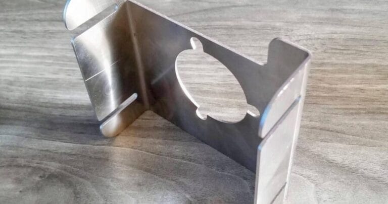
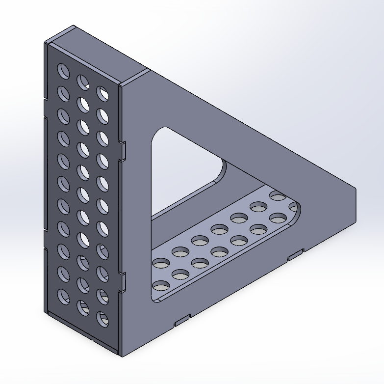
- The fabrication square in Figure 10 needs to be extremely accurate. It uses laser cut features to create a hard stop for locating other parts rather than relying on bend accuracy. Parts will be welded together in a way that minimizes warping.
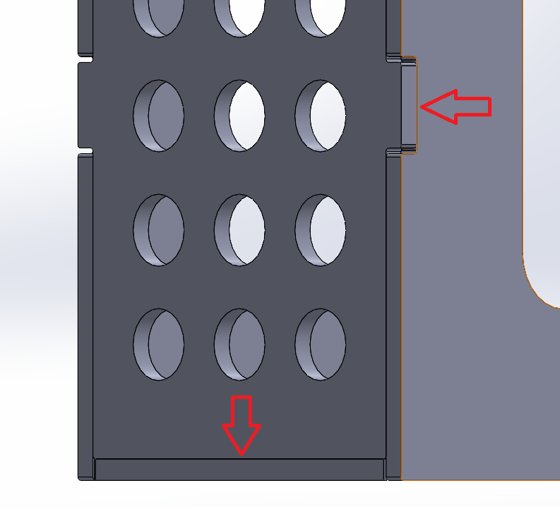
- Figure 11 shows that the tabs are floating on the top and bottom but are aligned to physically stop against the other laser-cut side plates. This method takes advantage of the precision of laser cutting to create self-fixturing assemblies that are more accurate.
Irregular parts
- Match bends to laser-cut parts.
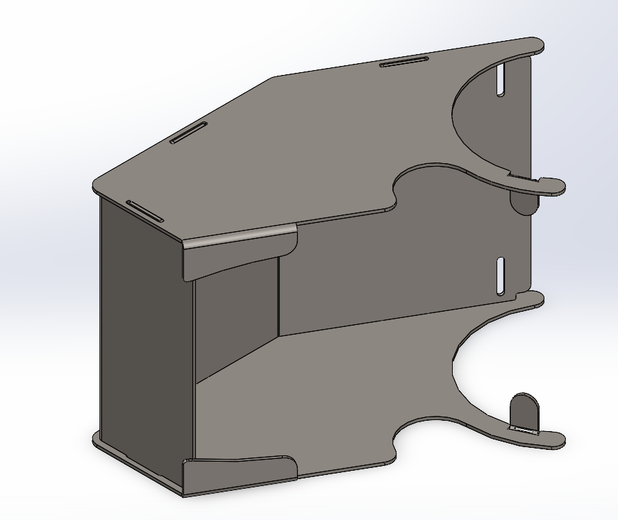
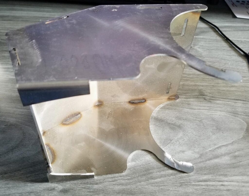
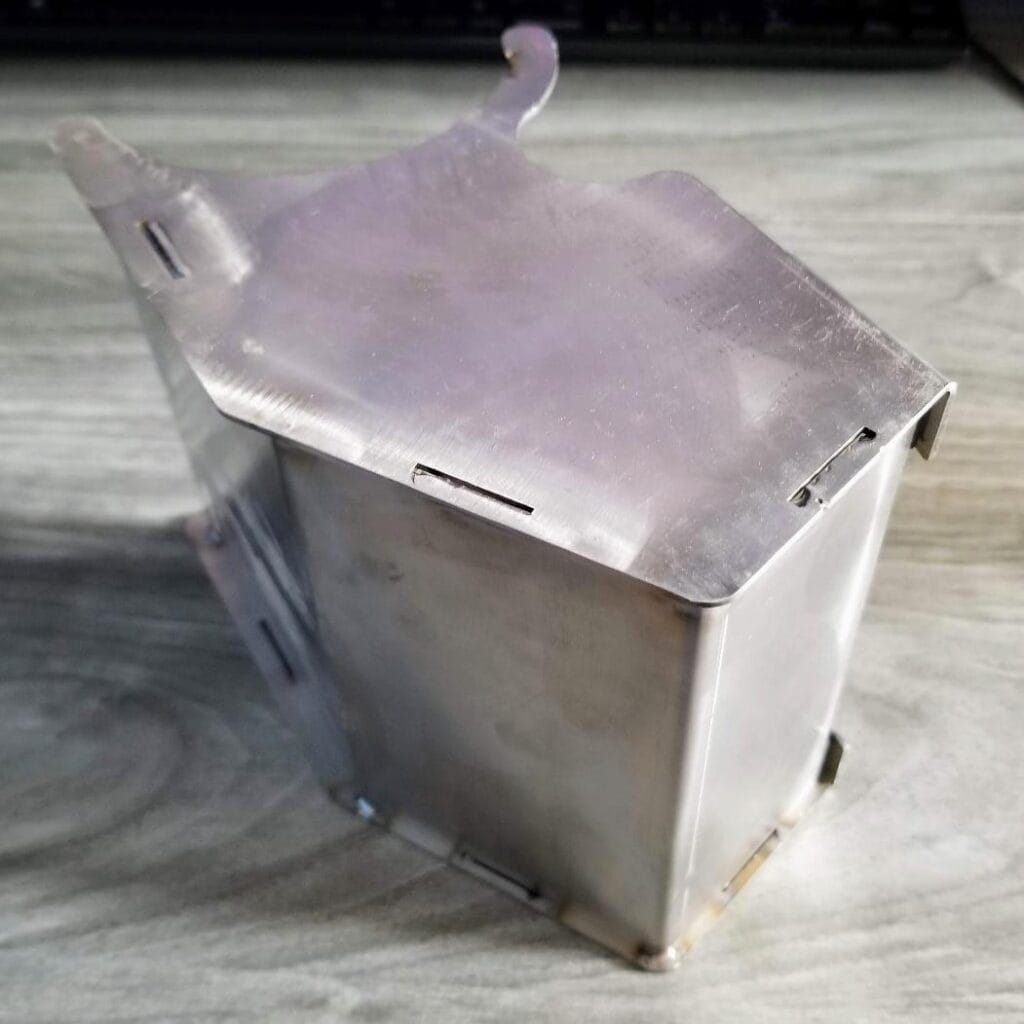
- Figure 12 shows a cover that requires accurate placement of bends.
- The slots in the top and bottom plates force the part into the shape required before welding, regardless of minor bend variations.
Tubes
- Match laser-cut parts to the diameter of tubes to create self-locating parts.
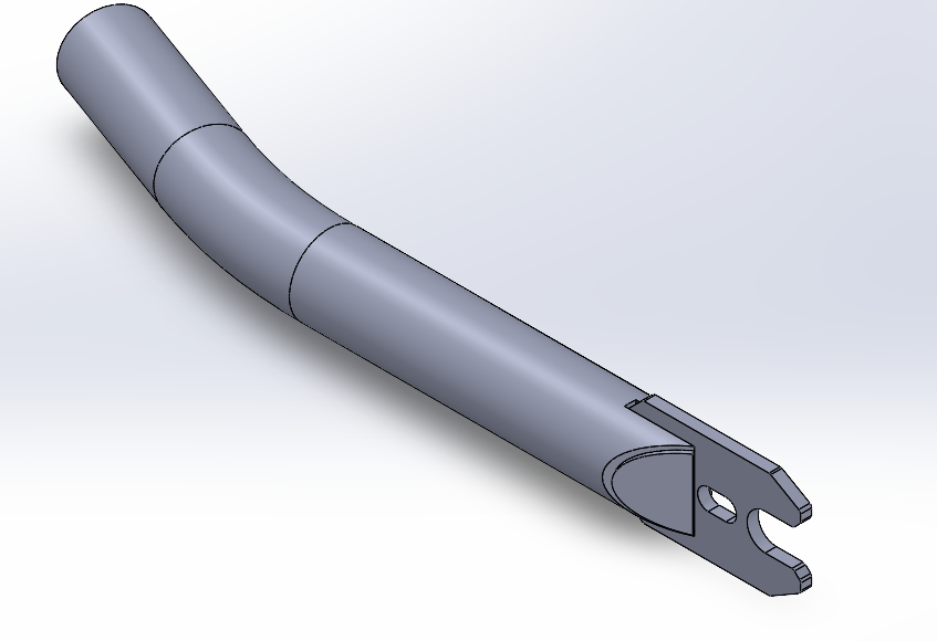
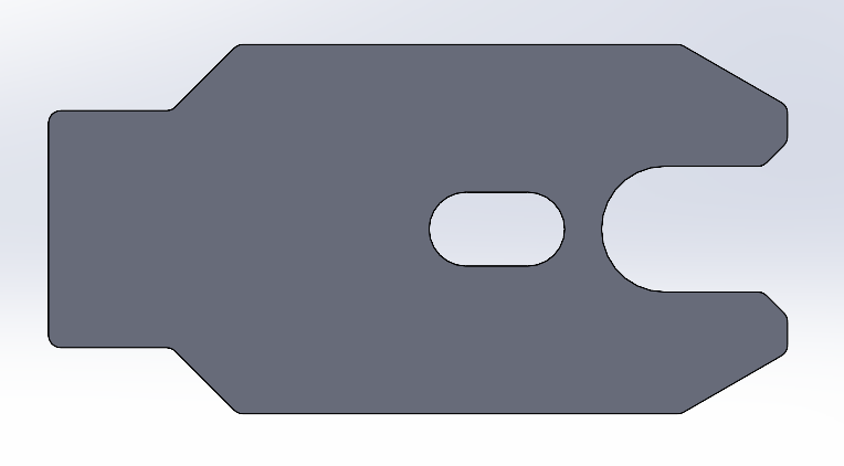
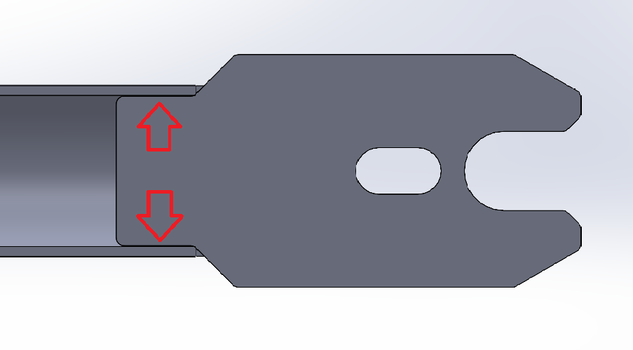
- Figure 12 shows half of a fork for a bicycle
- The dropout that holds the axle is designed to be self-fixturing by matching the inner diameter of the tube.
- The side caps were also laser cut to save time; all parts will be welded into place.
Considering Tolerances When Designing Sheet Metal Parts
In this age of digital manufacturing, fabricators, makers, and hobbyists alike all have access to the same cutting-edge manufacturing equipment used by professionals at a fraction of the cost. These machines are extremely accurate and repeatable but still have limits. Parts that are designed on a computer are a perfect case and do not account for machine tolerance, it is the job of the designer to consider how these expected variations could affect the final part. SendCutSend has a variety of services, all with unique processes and tolerances that should be assessed during the design phase. Laser cutting is one of the most precise ways to create flat parts and air bending is also very accurate but small variations can add up across large parts and multiple bends. There are a few tricks that professionals use to take advantage of laser cutting to create hard stops that increase the precision of bent parts and allow for self-fixturing.
Before uploading your design to SendCutSend, check out the services guidelines.


