There are a few ways to get bend data into flat files exported from SolidWorks. They all have to do with mapping bend lines into layers and linetypes. Prior to SolidWorks 2022, SolidWorks would put all bend lines into a layer called BEND. In SolidWorks 2022, this default was removed and bends now need to be mapped into flat files by the user. To do this, you need to enable custom mapping. The following directions explain how to enable this mapping, alongside two methods you can follow to create a DXF file with bend lines.
Please note that when bend lines extend across cut features, SolidWorks will export the bend line as separate segments instead of a continuous line. If you’d like to revise DXFs so bend lines are continuous before uploading your file for a quote, we recommend the free 2D program QCAD. We have a guide with QCAD setup and preflight tips here: How to Preflight Your Designs Using QCAD
*If you’re using SolidWorks 2021 or older, please reference this article for bend export.
Enable custom mapping from SolidWorks to DXF/DWG
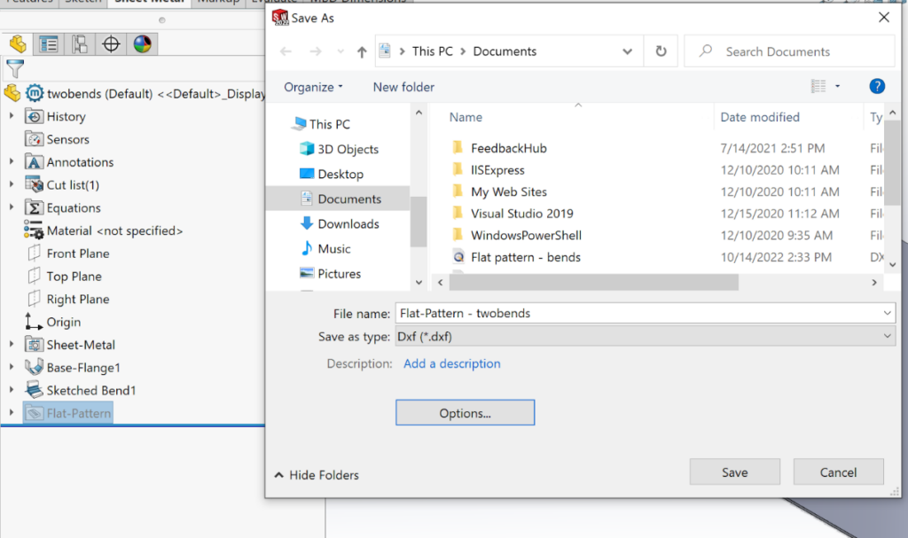
1. Right click the 3D model like you normally would to “Export to DXF/DWG”
2. Select “Export to DXF/DWG” and click the options button in the window that appears
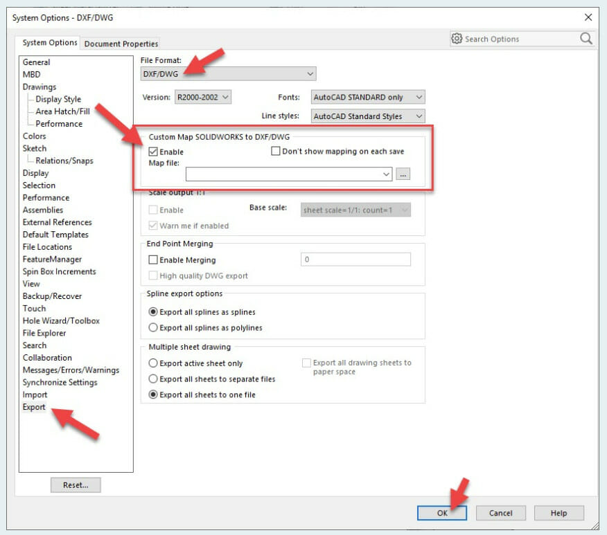
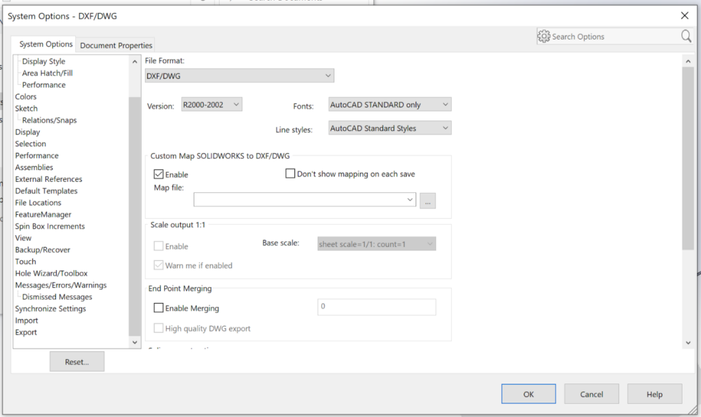
3. The System Options window will appear. Check enable under Custom Map SOLIDWORKS to DXF/DWG
[Option 1] Using SendCutSend’s map file
1. After enabling custom mapping from SolidWorks to DXF/DWG, download the SendCutSend SolidWorks map file: https://cdn.sendcutsend.com/docs/sendcutsend_solidworks_map
2. For the Map file option, choose the downloaded map file. Click on the button with three dots to locate the file.
3. Click ok and click save to export your flat pattern
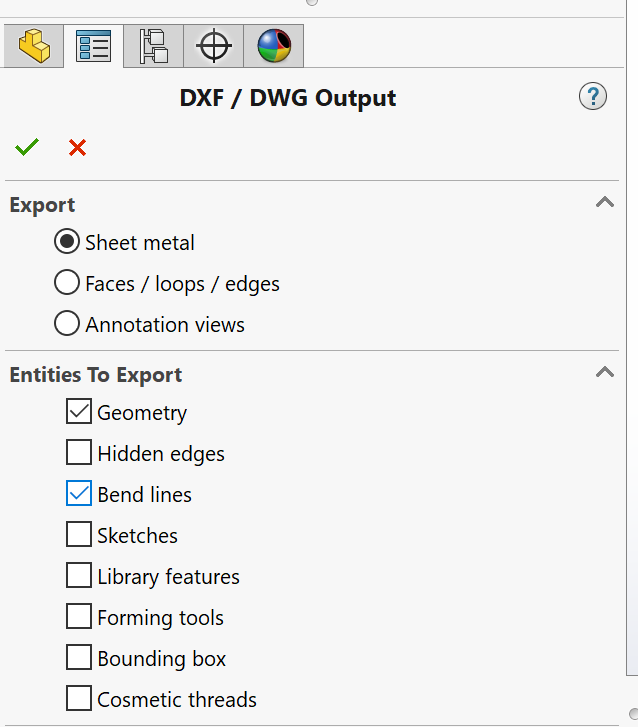
4. On the left side of the screen, the DXF/DWG Output window will appear. For export, select Sheet Metal
5. For entities to export, make sure that only Geometry and Bend lines are checked
6. Click the green check mark
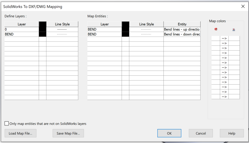
7. You’ll notice that your entities have been mapped according to SendCutSend’s map file.
8. Click ok. You’ll now see a preview of the DXF. Bend lines will be indicated by non-solid lines
9. Click save. Your flat file is now ready to be uploaded to SendCutSend
[Option 2] Mapping bend lines to a BEND layer
1. As before, be sure to enable custom mapping from SolidWorks to DXF/DWG
2. Click ok and click save to export your flat pattern
3. On the left side of the screen, the DXF/DWG Output window will appear. For export, select Sheet Metal
4. For entities to export, make sure that only Geometry and Bend lines are checked.
5. Click the green check mark
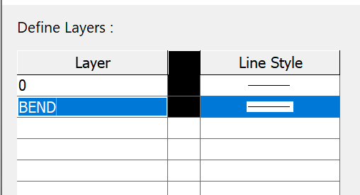
6. Under Define layers, Add a new layer called bend.
7. Under Map Entities:
8. Set the Entity to Bend lines – up direction
9. On the same line, set the Layer to the BEND layer created in step 6
10. Change the Line style to a Centerline type such as Section.
Important: make sure the Line Style is not Hidden.
Our system will not be able to detect Hidden bend lines.
11. Repeat the same process for Bend lines – down direction


12. Click ok. You’ll now see a preview of the DXF. Bend lines will be indicated by non-solid lines
13. Click save. Your flat file is now ready to be uploaded to SendCutSend
Check out our additional SolidWorks tutorials if you’re using SolidWorks for SendCutSend laser cutting services.
You should also check out our SolidWorks Plugin. You can upload to SendCutSend and get live quotes without ever leaving SolidWorks.
