The nature of bending sheet metal requires a high level of precision due to material stretch that is caused by bending and forming. This is unique to each material type, material thickness, and bend angle. Precise positioning of bend lines is very important in order to counteract the material stretch.
This article will explain how to use SolidWorks to create a precise DXF file for a bent sheet metal part. Before you begin, check out our SolidWorks Plugin. You can upload to SendCutSend and get live quotes without ever leaving SolidWorks.
We strongly recommend downloading our free gauge tables for SolidWorks! We have guidance on importing them here: How to Import and Use Sheet Metal Gauge Tables in SolidWorks
Our gauge tables allow you to easily use our bending specifications for the material you plan to quote. Each material thickness we bend has a set inside bend radius and K factor that cannot be changed.
Please note that when bend lines extend across cut features, SolidWorks will export the bend line as separate segments instead of a continuous line. If you’d like to revise DXFs so bend lines are continuous before uploading your file for a quote, we recommend the free 2D program QCAD. We have a guide with QCAD setup and preflight tips here: How to Preflight Your Designs Using QCAD
*If you’re using SolidWorks 2022 or newer, please reference this article for bend export.
How to Create Sheet Metal Bends in SolidWorks
Although you can use our handy parts builder to laser cut simple parts, specifying bend lines requires CAD software of some kind. Thankfully, it’s relatively simple to design for sheet metal bending in SolidWorks because of its easy-to-use sheet metal design features.
Let’s go through the general steps, before diving into a tutorial:
- Create a Base Flange/Tab: With a new part document open in SolidWorks, select a plane, and click the first button on the Sheet Metal toolbar to form a base flange.
- Dimension: Sketch and dimension your sheet metal part and click “OK”
- Base Flange parameters: This is where the important details happen, the default criteria for bend allowance is K-factor, and you can find the number for each material and thickness we bend on that particular metal’s Material Details page. For a deep dive into K-factor, see our Ultimate Guide.
- Add flanges: There are a couple ways to do this; by adding edge flanges, or sketched bends. SolidWorks makes both pretty simple.
- Export as DXF: SendCutSend can handle several file formats for bend lines, but the most straightforward is a DXF.
- Import and Configure: Drop that DXF in our app and check out this Guide to Configuring Bends.
Need that spelled out for you? Read on!
Calculating Sheet Metal Parameters
SolidWorks calculates the correct size of your sheet metal flat pattern based on bend allowance calculations. These can get pretty tricky, so see our Bend Allowance article for a deep dive into how to calculate them manually. SolidWorks does a lot of that bend allowance math automatically, so you can simply specify a parameter such as K-factor, bend deduction, or even use a bend table.
We’ve put together a bending calculator on our website, which is the best way to “check your work” after using Solidworks sheet metal to get a base flange and bend parameters. If you want guidance on utilizing the bending calculator, watch our video guide before finishing the rest of this tutorial.
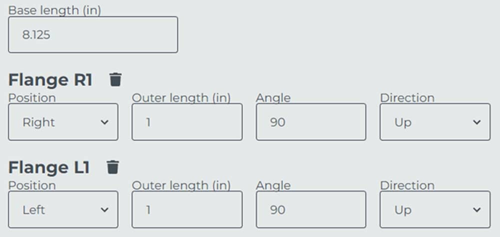
This example will use the bending calculator to find the parameters associated with a sheet metal part consisting of the following dimensions:
Base Length: 8.125”
Outer Flange Length: 1” (2 flanges, 90 degrees upwards)
Material: 5052 Aluminum (0.063” thickness)
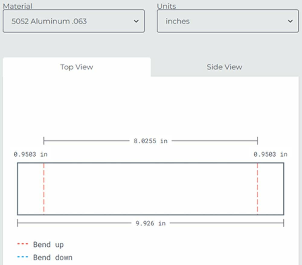
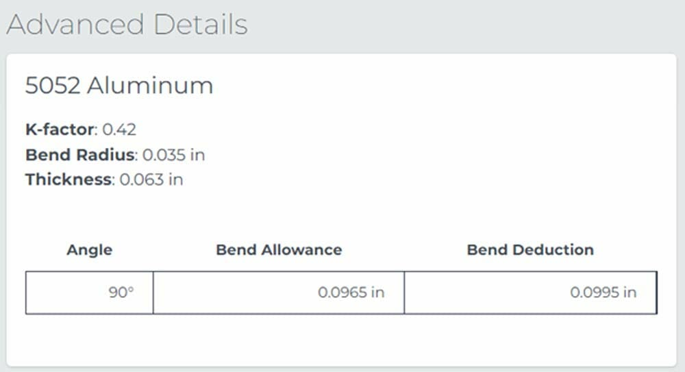
As seen, the calculator determines the appropriate placement of the bend lines and required total length of the flattened sheet metal part. This is unique to each material type, material thickness, and bend angle. The results for the K-factor, bend radius, and thickness are shown below:
Creating a 3D Sheet Metal Design in SolidWorks
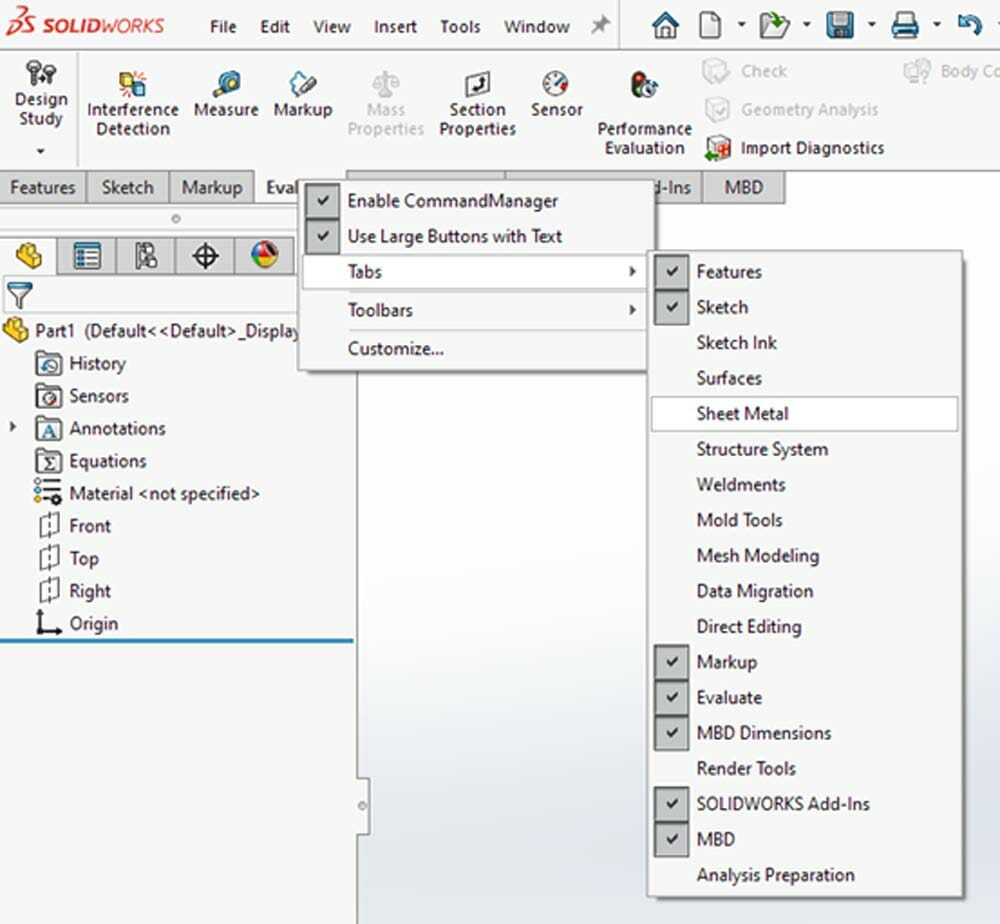
Open SolidWorks and look at your available tabs. If you do not already have a “Sheet Metal” tab available, make sure to include it by right-clicking any tab, and toggling on the Sheet Metal tab.
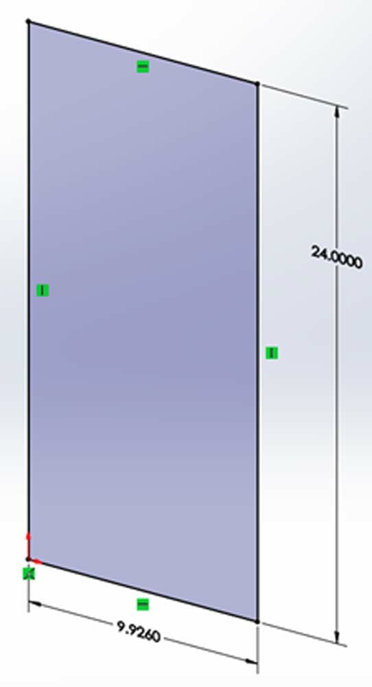
Now that the Sheet Metal tab is available, create a sketch like you normally would that is appropriately dimensioned according to the “Top View” of the SendCutSend bending calculator. The bend lines are added at a later time. The length of this sketch is arbitrary. A length of 24” is selected for the purposes of this tutorial. This sketch represents the overall size of the “flattened” part. After dimensioning, click the green check mark, but do not exit the sketch.
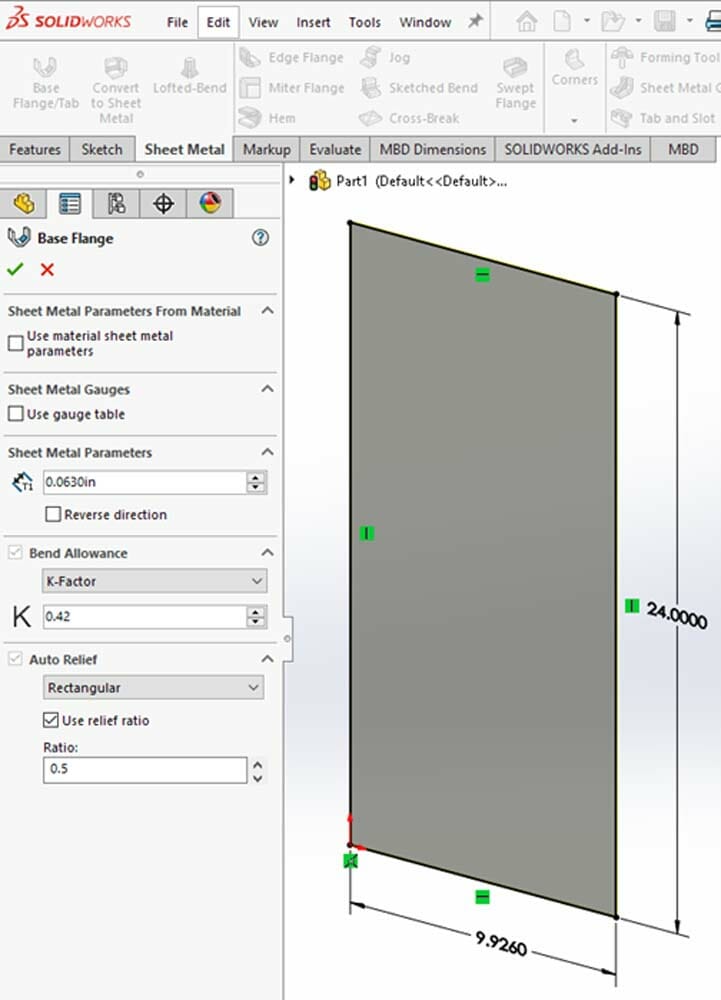
Next, you need to specify the sheet metal properties. In the “Sheet Metal” tab, select the “Base Flange/Tab” button to specify the sheet metal properties that were calculated from the bending calculator. When complete, select the green checkmark. This creates a new sheet metal part.
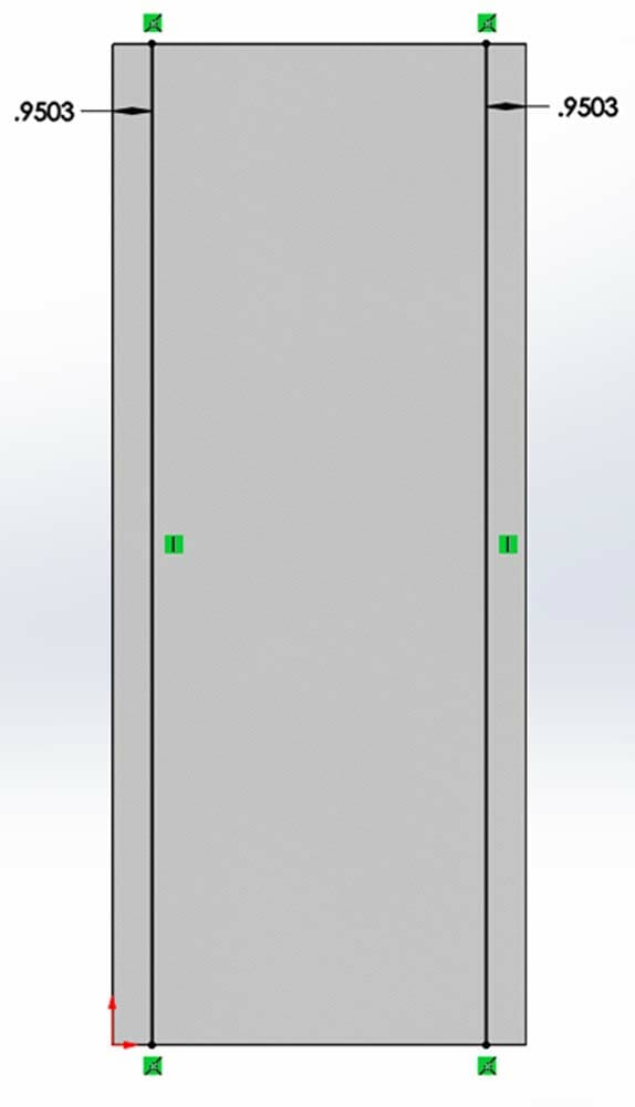
With the sheet metal part created, it is time to start the process of bending in SolidWorks. To do this, create a new sketch with lines representing where each of the bends occur and appropriately position them according to the dimensions in the SendCutSend bending calculator results. Click the green check mark and Exit Sketch.
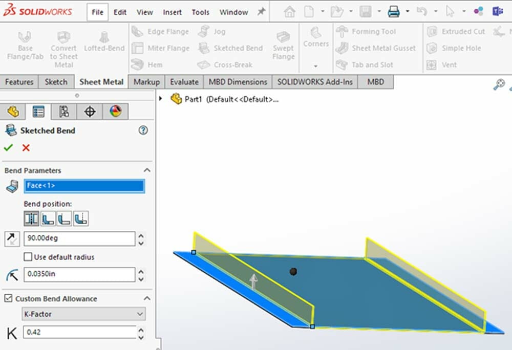
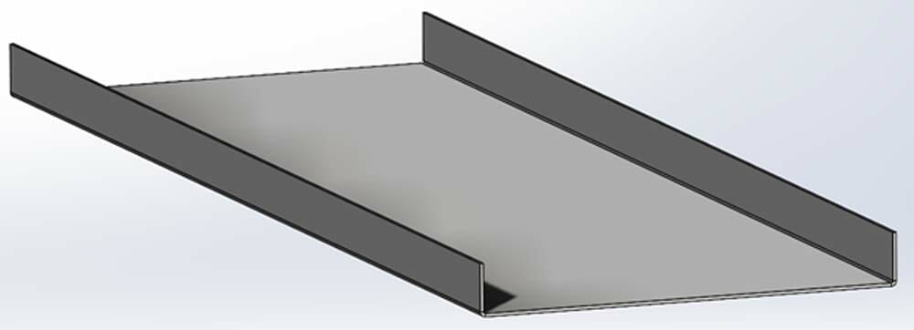
To insert bends, go back to the Sheet Metal Tools tab and select “Sketched Bend.” Then select the line sketches from the previous step. SolidWorks then gives a new dialogue box option to select the faces that will be “fixed” or act as the base flange. In this case, there is only one face that is fixed, which is the base. Once the base is selected, the sheet metal part is bent at the sketched lines, and two flanges are created. The bend angle, bend radius, and K-factor can be specified here in the property manager according to the SendCutSend bending calculator results. The “Bend Position” setting is left as “Bend Centerline” which is consistent with SendCutSend bending methodology.
Export to DXF
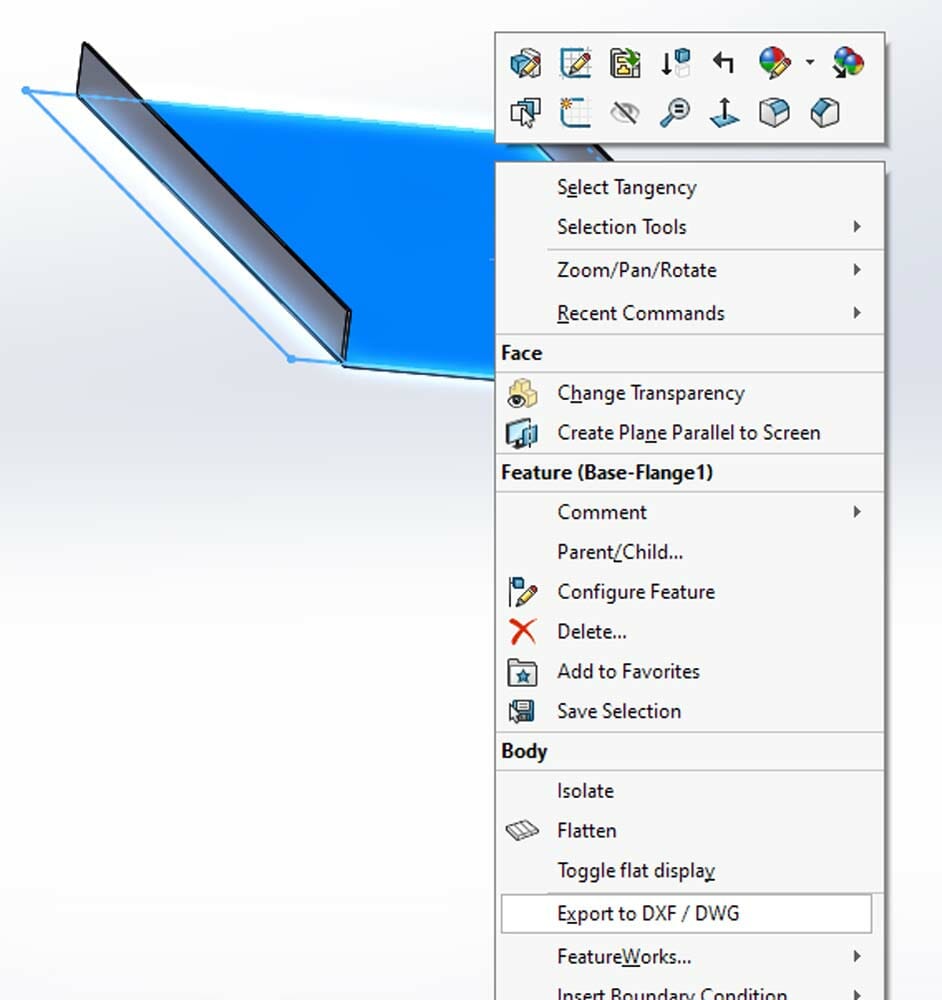
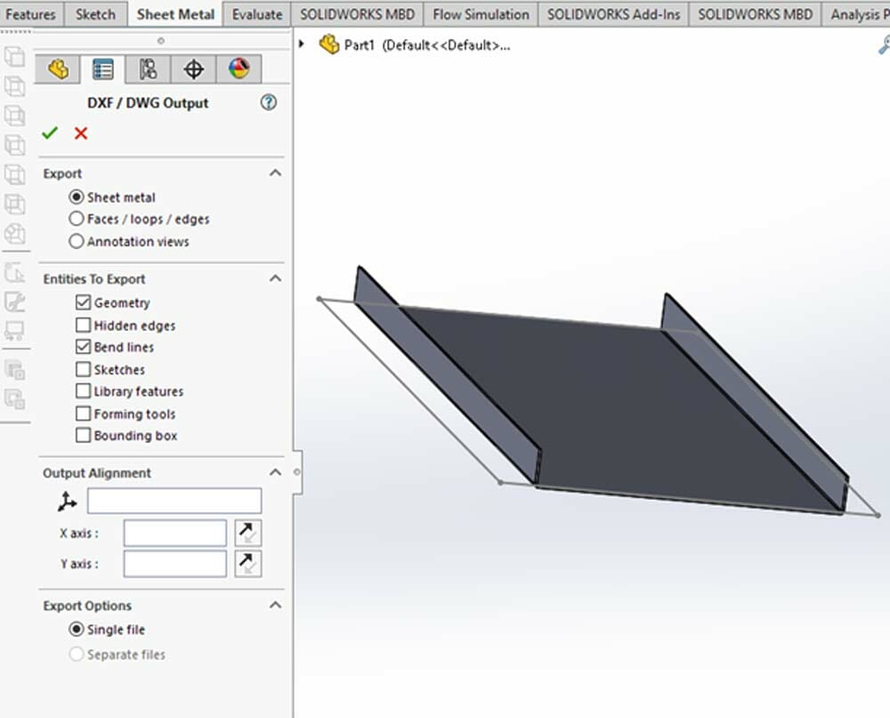
After you’ve completed the design you’ll need to create a DXF to upload for quoting. To export to DXF, right click any face on the 3D model. Select “Export to DXF/DWG” in the dropdown menu.
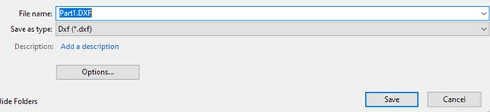
After saving the DXF file, SolidWorks prompts a new menu to the left. Under “Export”, make sure “Sheet Metal” is selected and also choose “Geometry” and “Bend Lines”.
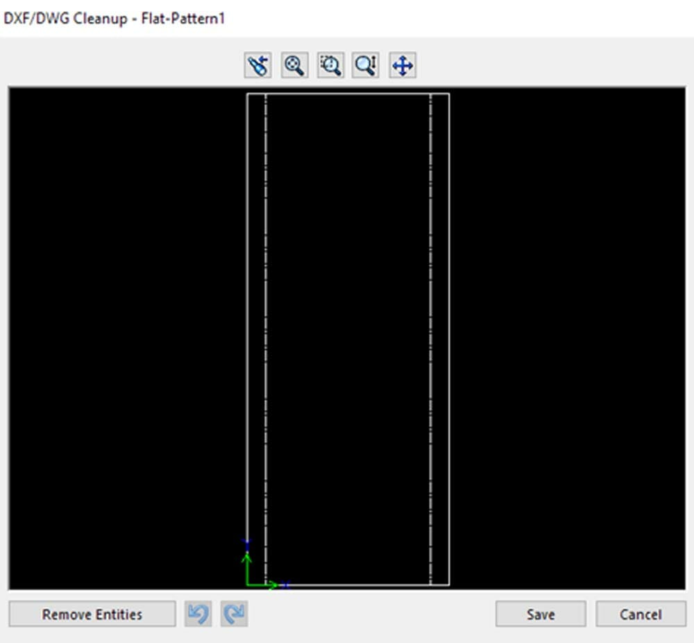
Click the green check mark and a preview of your flattened part will appear. Confirm that everything looks the way it should, click save, and you’re just about ready to upload your part for quoting.
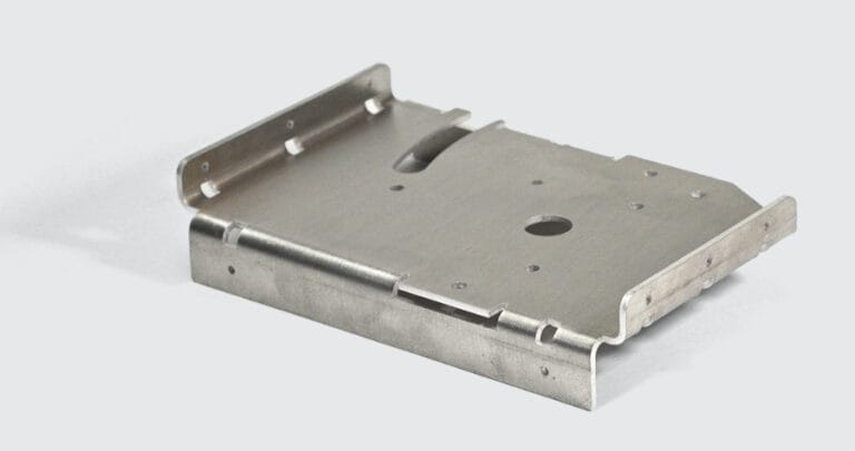
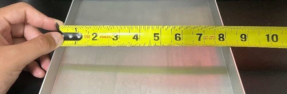
As a test, this exact DXF file was used to order through SendCutSend.
The measurement of the base length matches exactly to 8.125″ thanks to the adjustments made according to the bending calculator.
Get Your Bend Right and Get a Quote
The sheet metal design feature in SolidWorks is very useful to create accurately designed DXF files. It is a wonderful tool to use in conjunction with the SendCutSend bending calculator. As with all bent sheet metal designs, be sure that your part fits within our bending guidelines to ensure a successful outcome.
Once you have your DXF file and have checked it against our guidelines, upload the file to our app. Pick your material and quantity, define the bends and bend angles, and you’ll see a quote for your parts instantly.
If you have any questions, just reach out to our support team!
