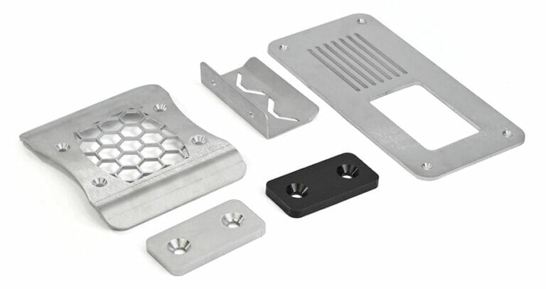
At SendCutSend we know your laser cut parts will eventually need to join up and create something awesome. That’s why we offer tapping, countersinking, and PEM hardware insertion to make assembly easier! Our minimum hole distance specifications are intended to ensure smooth processing so you’ll receive successful parts, fast.
If your next project could benefit from SendCutSend’s hole operation services, this article will help you apply our specs to your design before placing an order. Follow our guide and your parts should move through production without delay.
Measure From Hole Centers
We generally prefer to measure minimum cut feature proximity distances from the center of a hole that requires services. Why?
Automatic hole resizing.
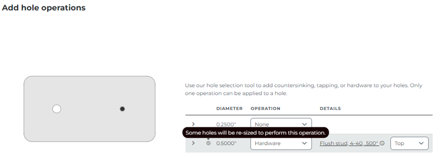
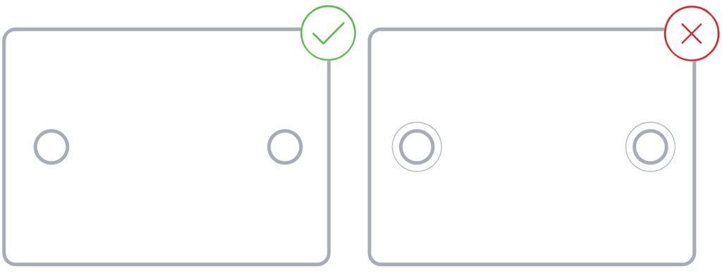
To ensure that hole operations are successful, we automatically resize holes to the perfect diameter for the tap, countersink, or hardware size you choose while configuring your part.
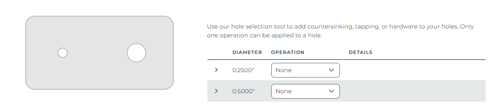
After you upload your design file to our website, select a material that is eligible for the hole operations you need and add hole operations, you’ll be able to see the resized hole in the part preview.
Before Adding Hole Operations
After Adding Hole Operations
However, this is only possible for circular holes up to 4.000” in diameter. Holes 4.001” or larger will not be selectable for hole operations.
Because we automatically resize holes, it’s best to measure the minimum distance required from the center of the hole rather than the edge. This ensures that no matter what size the hole is in your design file, it will always be far enough away from other cut features.
Finding Operation Specifications
You can find all critical specifications for every operation on the individual material pages in our Material Catalog. Find the material you need for your project and scroll down to the Material details and specifications. Then select your desired stock thickness and click View Specs to see the hole operation minimums.
For example, take a look at 0.125” 5052 aluminum. This material and thickness is eligible for all hole operations.
Tapping Minimums
For tapping services, we provide Tapping Min Hole to Edge and Tapping Min Hole Center to Material Edge specifications.
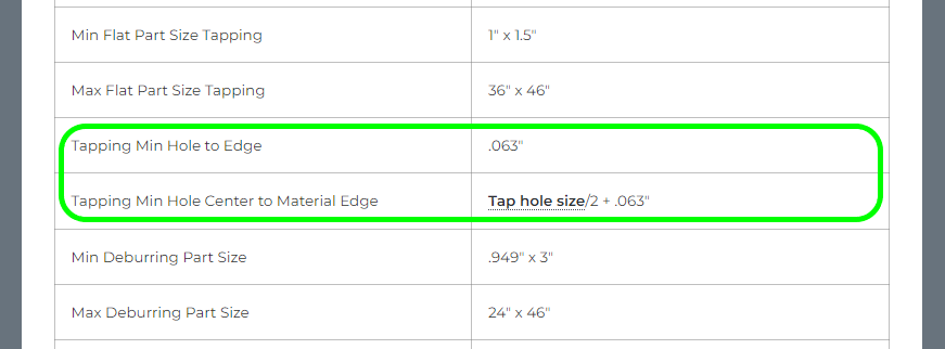
Tapping Min Hole to Edge: minimum distance from the edge of a tapped hole to an adjacent cut feature. You can also think of this as the minimum amount of bridging/webbing required between the edge of a tapped hole and another cut feature.
Tapping Min Hole Center to Material Edge: minimum distance from the center of a tapped hole to the edge of an adjacent cut feature.
The tapping min hole center to material edge value will depend on the tap size you need. If you click the tap hole size link, you’ll be brought to the Thread/Tap Hole Size Chart on the tapping guidelines page.
The chart shows the diameter that holes will be resized to for each tap size.
Center of Tapped Hole to Edge
To calculate the minimum distance from the center of your tapped holes to the nearest adjacent cut feature,
- Find the tap size you need for your part
- Note the hole size for that tap size
- Divide the hole size by 2
- Add that value to the Tapping Min Hole to Edge value for the needed material thickness
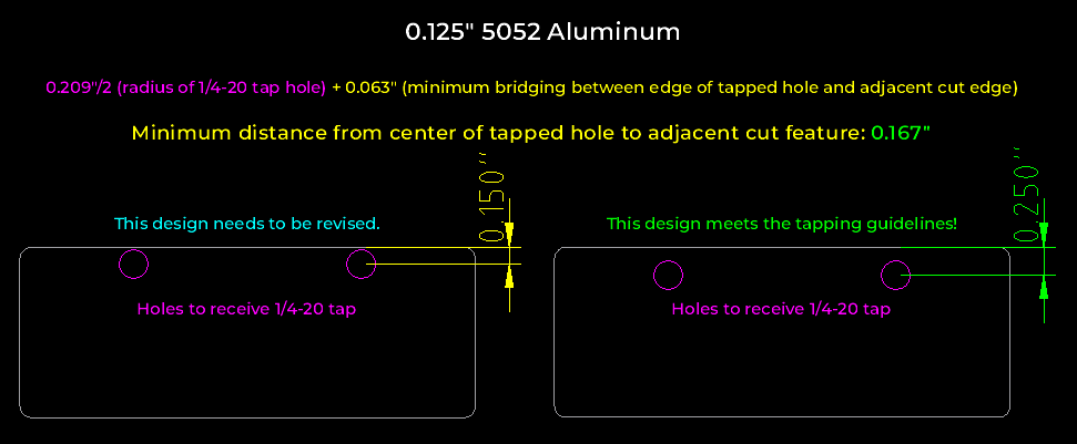
For example, if we wanted to a part in 0.125” 5052 aluminum to receive 1/4-20 size taps.
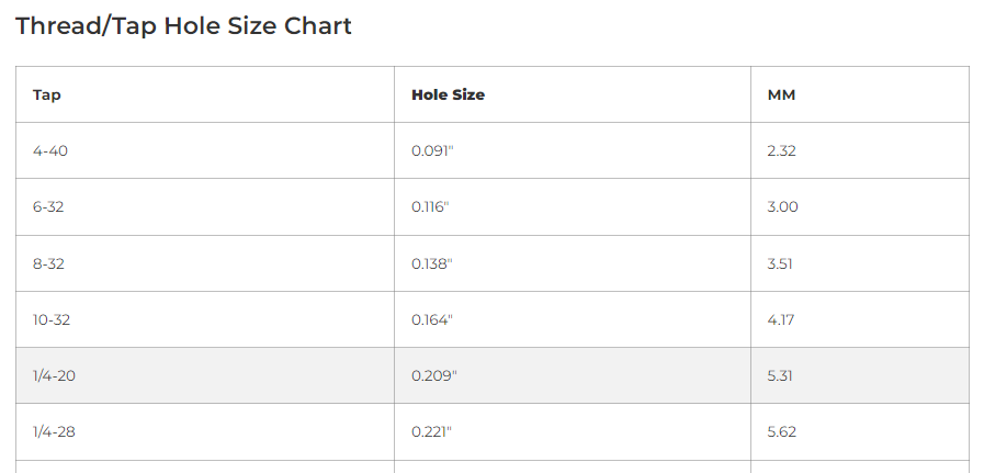
We’d need to calculate 0.209”/2 + 0.063” to find the minimum distance from the center of the tapped holes to the nearest cut feature.
The minimum distance for a 1/4-20 tap in 0.125” 5052 aluminum is 0.167”.
Then, measure the distance from the center of the hole to be tapped to the nearest cut edge. If the distance is less than the minimum, either the hole will need to be moved away from the adjacent cut feature, or you’ll need to determine if a smaller tap size could work for your part.
Tapped Hole to Tapped Hole
If you need to confirm whether two tapped holes are a sufficient distance apart, calculate the minimum distance from center of hole to center of hole by adding the required hole radius for tap 1 + required hole radius for tap 2 + Tapping Min Hole Center to Material Edge value for the material.

Countersinking Minimums
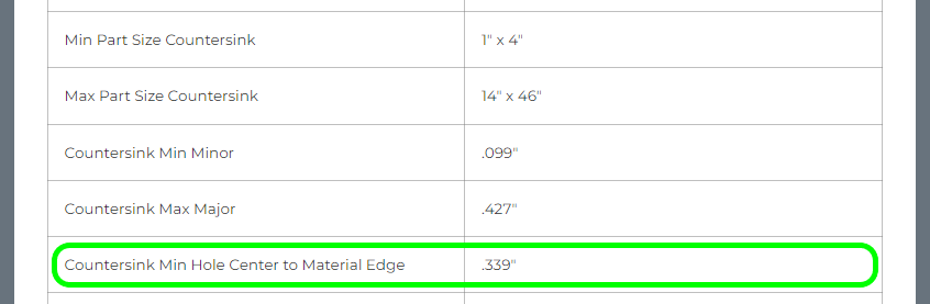
We provide a Countersink Min Hole Center to Material Edge value for each material and thickness that is eligible for countersinking services. Depending on features that are adjacent to your countersunk holes, this value may or may not be applicable.
Center of Countersink to Edge
Use the Countersink Min Hole Center to Material Edge value to measure the distance between the center of a countersunk hole and the edge of your part or any large cutouts.
Countersink to Countersink
When it comes to adjacent countersinks, those holes can get fairly close! There are just a few considerations to keep in mind.
- Major Overlap
- The majors of two countersinks should not overlap
- The majors of two countersinks should not overlap
- Minor Proximity
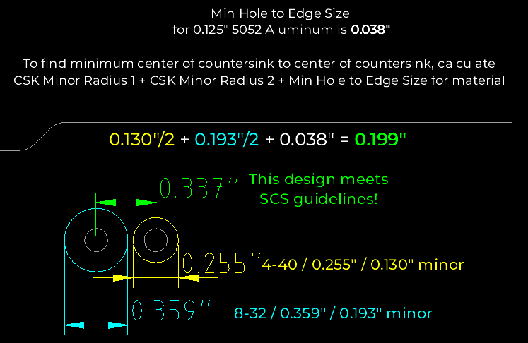
- The minors of two countersinks must be at least the Min Hole to Edge Size away from each other. This value refers to the minimum amount of bridging/webbing required for the material between a circular hole and an adjacent cut edge.
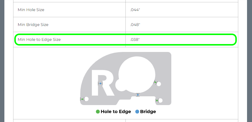
- To find the minimum distance from the center of one countersink to the center of another countersink, calculate CSK Minor Radius 1 + CSK Minor Radius 2 + Min Hole to Edge Size for material.
Countersink to Tapped Hole
Countersunk and tapped holes can get pretty close, too! The proximity considerations are similar:
- Major Overlap
- Countersink majors should not overlap tapped holes
- Countersink majors should not overlap tapped holes
- Minor Proximity
- The minors of countersinks must be at least the Tapping Min Hole to Edge away from each other. This value refers to the minimum amount of bridging/webbing required for the material between a tapped hole and an adjacent cut edge.
- To find the minimum distance from the center of a countersink to the center of a tapped hole, calculate CSK Minor Radius + Tap Hole Size Radius + Tapping Min Hole to Edge for material.

Hardware Minimums
When hardware is the best solution for your project, be sure to consult the following resources:
- SendCutSend Hardware Installation Guidelines
- Hardware Catalog – SendCutSend
- SendCutSend Material Catalog
Our guidelines page includes best practices, design parameters, and results you can expect from SendCutSend hardware installation. Minimum distance information can be found in our Hardware Catalog.
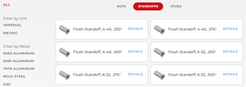
Hardware Catalog
For hardware-to-edge, hardware-to-bend, and hardware-to-hardware distance minimums, find the fastener type and size you need at the hardware catalog and click to find its specifications.
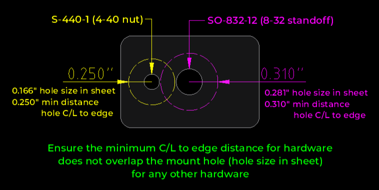
There are a few values on each hardware spec sheet to look out for: hole size in sheet, center of hole to edge or bend, and hardware-to-hardware.
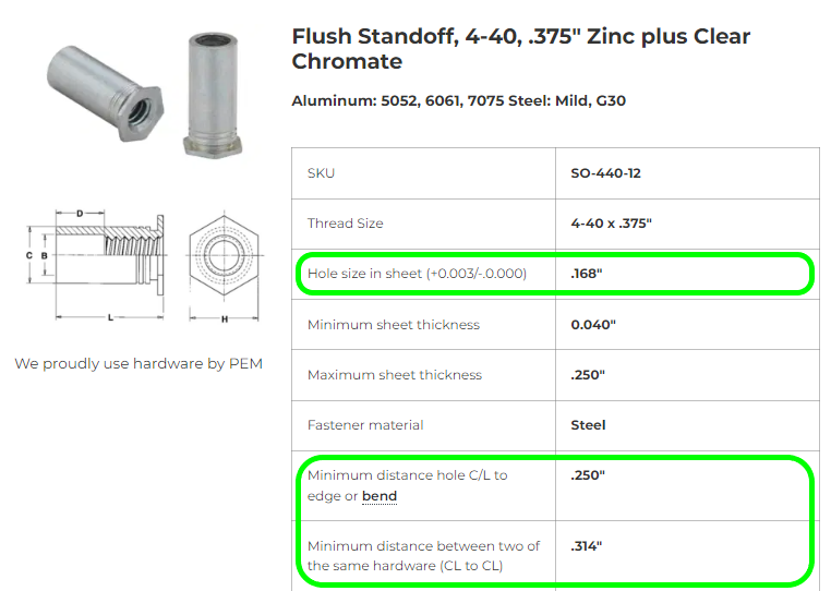
Hole size in sheet
Please note that when you add hardware to a hole while configuring your part, it is automatically resized to the Hole size in sheet value shown in the hardware catalog (+0.003”/-0.000”).
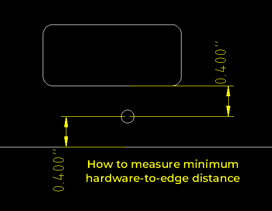
Center of hardware hole to edge or bend
Minimum distance hole C/L (centerline) to edge or bend is the minimum distance from the center of a hardware mount hole to the edge of an adjacent cut edge or bend. This applies to any material the hardware is being inserted into.
Measuring hardware-to-bend distance comes with additional considerations.
Hardware to hardware
This row instructs that when determining the distance between two or more fasteners, you can calculate the distance by the following formula:
Minimum distance hole C/L (centerline) to edge + ½ the diameter of the second mounting hole
The value given is based on two hardware of the same size.

While the minimum center-of-hardware-hole to center-of-hardware-hole distance is provided on the spec sheet, the value provided assumes that the hardware size is identical.
For two differently sized adjacent hardware, ensure that the minimum distance C/L to edge for either hardware never overlaps the hardware mount hole (hole size in sheet) for the other.
Material Info Page
Check your desired material’s information page to confirm material-specific limitations for hardware installation under Material Details.
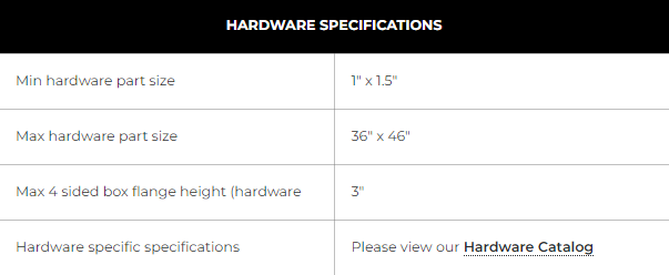
Hardware minimum and maximum overall flat part sizes can also be found at the Processing Minimum and Maximum Sizes chart.
Proximity to Bends
If tapped, countersunk, or hardware insertion holes are too close to bend lines (lines in your design marking the center of each bend), the holes will be distorted. We have detailed information about cut feature proximity to bend lines here: Bending Deformation Guidelines
Tap or Countersink to Bend Line
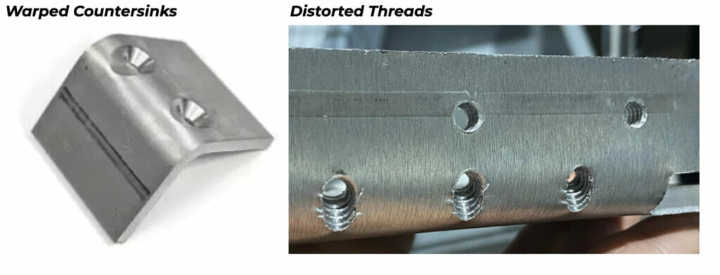
Since we tap and countersink holes before bending parts, any tapped or countersunk holes that fall within the die lines of our tooling will be distorted and the benefits of those services may be negated (unusable threads or warped countersinks).
To avoid distortion, ensure that tapped holes and the major diameter of any countersunk holes are at least half the die width away from the bend line, measured from the flat pattern.
Check out our detailed die line considerations explainer here: Die Line Considerations
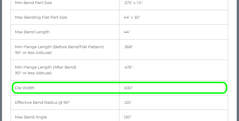
The full die width of the tooling we use for each material and thickness is listed on each material info page.
For example, in 0.125” 5052 aluminum, the bottom die width is 0.630”.
Here is an example of a part in 0.125” 5052 aluminum that prevents distortion by placing tapped and countersunk holes at least 0.315” away from the bend line.
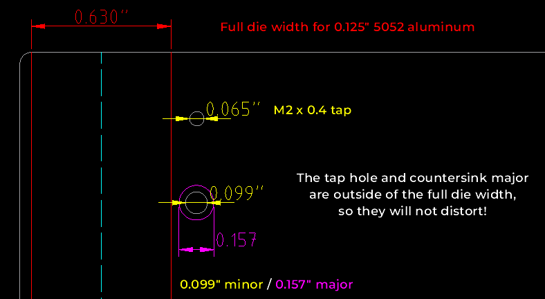
Per our countersinking guidelines, only the minor hole should be included in your flat file (DXF, DWG, EPS, or AI format).
Confirm the major will not fall within the die width before you export your design, and be sure to remove the major diameter and/or check that it will not be included before exporting. Take a look at our guides here: SendCutSend Export Guides
If You Insist
Please note; we can bend laser cut parts with tapped or countersunk holes that will be warped. However we may put your order on hold and contact you to confirm if you accept distortion due to bending for those holes.
If you’d like your order to move through production as quickly as possible, it’s best to ensure tapped holes and countersink majors are outside the die lines of our tooling and will not distort.
Hardware to Bend Distance
For successful hardware insertion, holes must be at least the bend allowance/2 + minimum distance hole C/L to edge away from the bend line (center of bend or apex) for the hardware size desired.
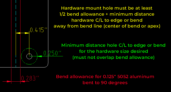
Confirm the bend allowance using our Bending Calculator. Input the material thickness and bend angle to find the correct bend allowance in the Advanced details.
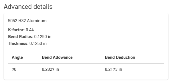
Confirm the minimum distance hole C/L to edge or bend distance for the hardware size in our Hardware Catalog.
Then, measure from the center of the hardware mount hole to the center of the bend in your design to ensure the hardware is at least the minimum distance away from the bend.
If a hardware hole is too close to the bend, it can warp during the bend operation (creating difficulty with snug insertion) or present proximity issues during attempted hardware installation. Learn more about considerations like this in our Guide to Planning Features Around Bend Lines – SendCutSend
Conclusion
Now you know how SendCutSend’s hole distance specifications for tapping, countersinking, and hardware insertion are intended to be applied! With this guide in hand you can’t go wrong when planning fastener placement for your laser cut parts. For more information about these services, check out all of our hole operation articles here. Happy fastening!


