In this tutorial, we’ll show you how to prepare text for laser cutting in Autodesk Fusion. Follow along with the video or this article to learn how to prepare laser cut text in Autodesk Fusion in just a few simple steps.
Video Guide to Creating Laser Cut Text in Autodesk Fusion
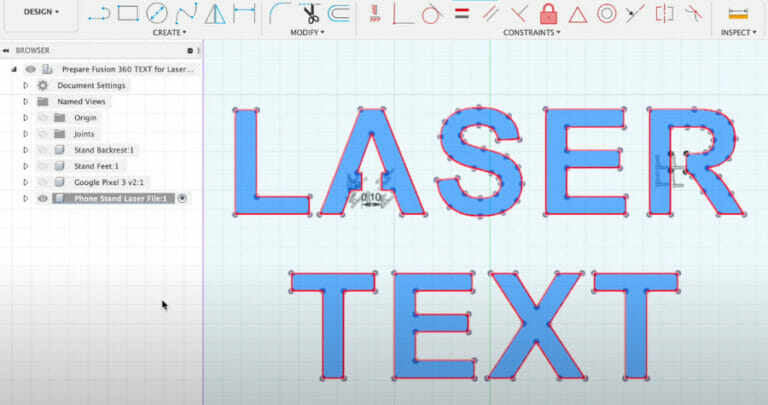
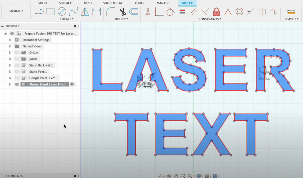
Before uploading your design to our Instant Quote tool, make sure to double check any text. In the below example, the word “LASER” includes two “islands” or areas of negative space; one in the letter “A” and “R”. These areas will not remain in the final design unless we bridge or join them to the main contour. Fortunately, this is an easy process in Autodesk Fusion.

Connect Negative Space to the Contour
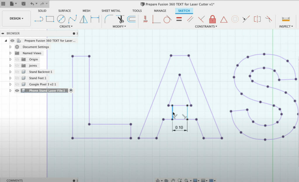
We can use the Line Command in the Sketch Tab to connect the negative space to the rest of the contour.
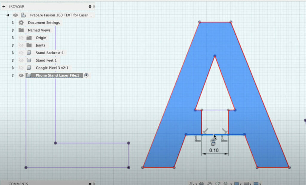
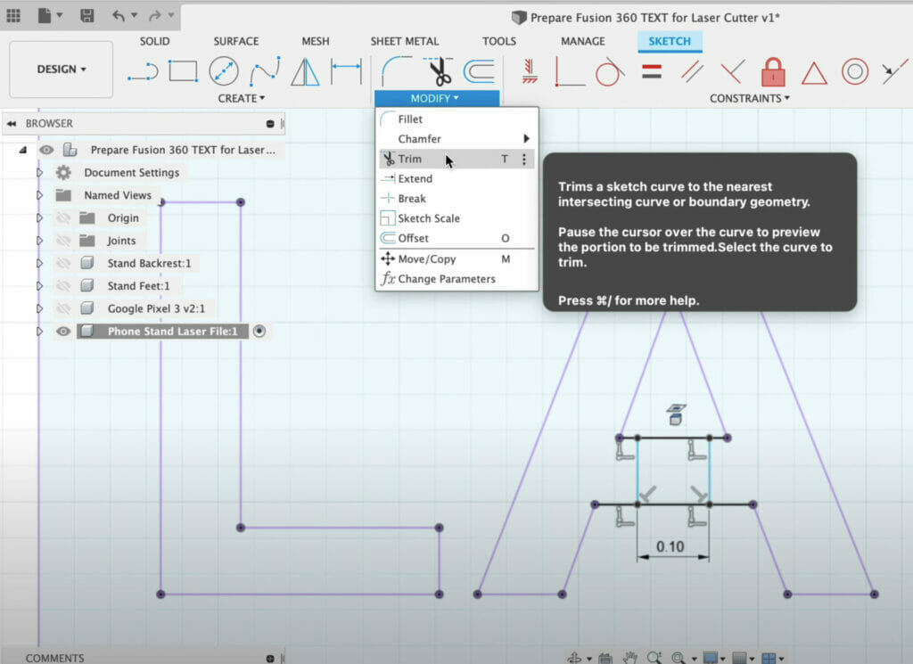
Use dimensions and constraints to place the line geometry as desired. Use the dimension command to set the width. In this example, we set the width to 0.10″. Keep in mind this thickness must be reasonable for your material of choice and your material thickness.
After this, it’s critical to trim away any unwanted lines so you’re left with a clean contour path. This includes the original geometry that makes up the A shape.
Break the Connection Link
In our example, the geometry was original projected so we’ll need to break the projection link. Working with text is one scenario where breaking the projection link is unavoidable.
To break the projection link, hold down the Shift key and select any pieces of geometry that need to be trimmed.
You can then select the Project Icon followed by the Delete key
The icon can be difficult to select, so we prefer to right click, followed by the Break Link option
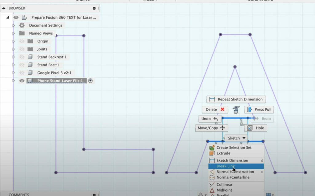
Both options will remove the projection link turning the geometry into standard sketch geometry. This changes the line color from purple to black.
Activate the Trim Tool
Next we can activate the Trim Tool from the Modify dropdown.
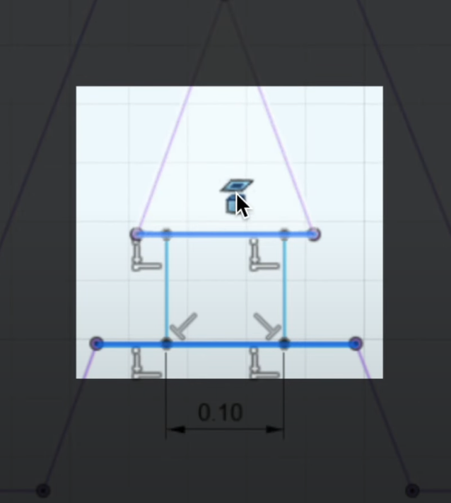
The Trim Tool allows you to quickly select line segments to trim away to their nearest intersection. In the below example, we’ve selected the bottom and top.
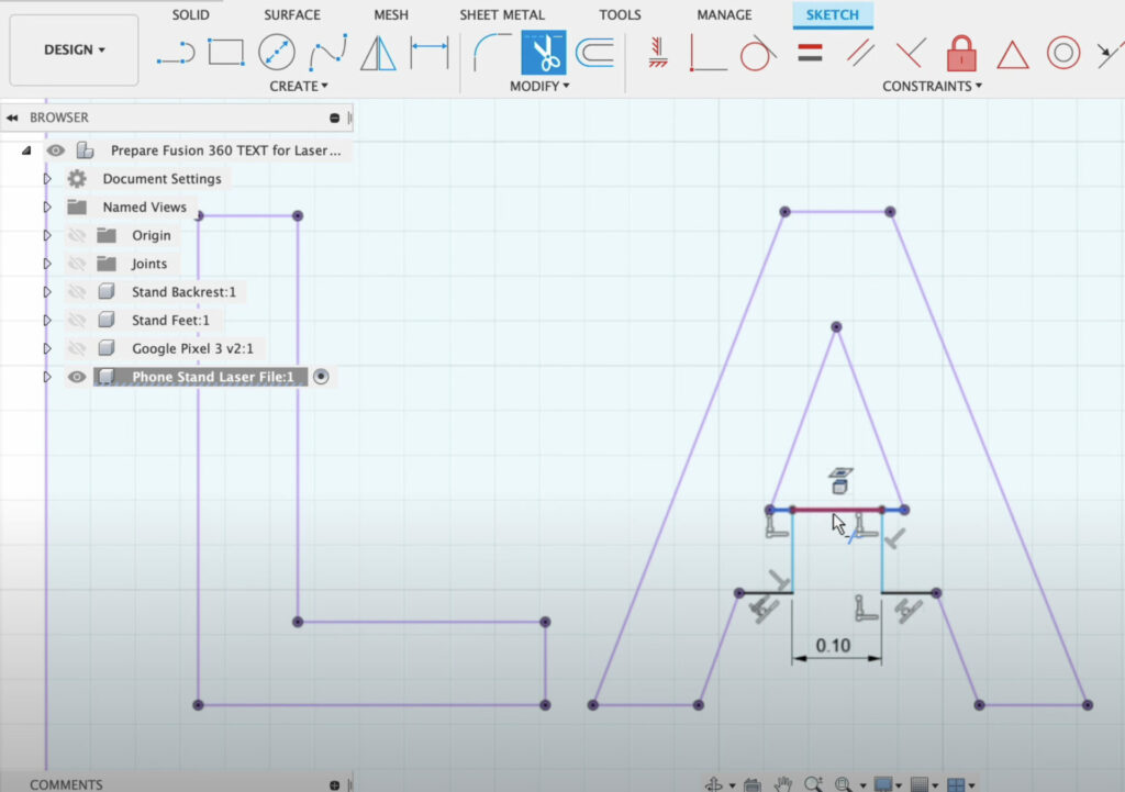
Depending on your constraints and dimensions applied, you may get some warning messages in the lower right corner. This is nothing to worry about but you should be cautious and keep an eye on what you’re removing.
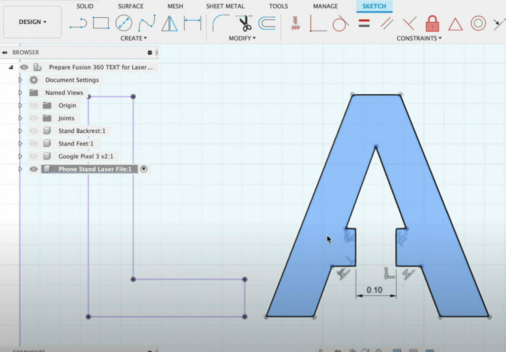
Our letter “A” is now ready to be cut on a laser cutter. Be sure to double check that it’s a closed profile but selecting the inside contour.
Repeat These Steps
You’ll need to repeat this process for all letters that include an “island” or negative space.
To summarize, we bridged the negative spaces in our text to make sure they could be cut by the laser cutter without losing the inner islands of specific letters.
Your Fusion design is now ready to be exported as a DXF for our laser cutter.
Check out our blog for more tutorials on Autodesk Fusion.
