12 Thicknesses
Production Time

Laser cut, +/- .005" tolerance
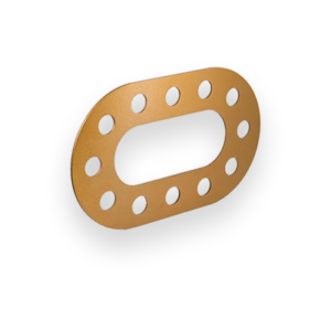
6061 T6 Aluminum is strong and lightweight. Our laser cut 6061 aluminum is commonly found in structural applications where toughness and corrosion resistance are of high importance. That’s pretty typical for aluminum alloys in general, but what makes this 6061 series stand out is its heat-treatability. The heat-treating process, called precipitation hardening, further strengthens the alloy without robbing it of key properties.
Many of our aluminum alloys are able to withstand tremendous amounts of vibration (also known as fatigue strength) making them perfectly suited for high-impact applications such as transportation and robotics. For any of these applications 6061 aluminum is a good middle of the road alloy, pairing the strength of 7075 with the malleability of 5052.
We guarantee awesome quality parts. If you’re not 100% happy, we’ll give you a refund or remake on the spot – no questions, no hassle.
SendCutSend offers 6062 T6 Aluminum in 12 thickness options: .040″ (1.02mm), .063″ (1.60mm), .080 (2.03mm), .100″(2.54mm), .125″ (3.18mm), .187″ (4.75mm), .250″ (6.35mm), .313(8.0mm), .375″(9.5mm), .500″ (12.7mm), .625 (15.88), and .750 (19.05)
When ordering 6061 T6 Aluminum through SendCutSend, there are specific size and thickness parameters to keep in mind. For instant quoting, the smallest part size available is .25″ x .375″, while the largest part supported is 30″ x 44″. For larger projects, custom quotes are available for sizes up to 30″ x 56″.
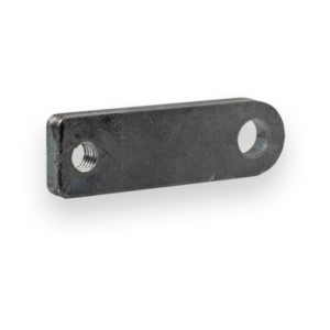
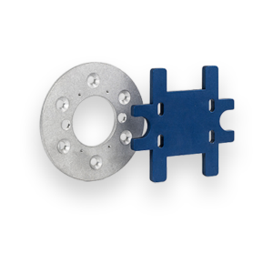
You can add the following services to your 6061 T6 Aluminum parts:
Anodizing, Countersinking, Deburring, Dimple Forming, Hardware Insertion, Powder Coating, Tapping, and Tumbling
We accept .ai, .dxf, .dwg, .eps, .stp, and .step
Customize one of our simple parts templates

6061 aluminum is one of the most popular and versatile alloys in the 6xxx series. Known for its excellent balance of strength, machinability, and corrosion resistance, 6061-T6 aluminum is used everywhere from aerospace brackets and automotive parts to consumer products and custom enclosures. At SendCutSend, we offer laser cut 6061-T6 aluminum sheet metal in a range of thicknesses, combining tight tolerances with quick turnaround times. Below, we’ll break down the key properties, benefits, and considerations for designers and fabricators using 6061-T6 in their projects.
The T6 temper of 6061 aluminum is solution heat-treated and artificially aged to its highest strength condition. It provides an excellent strength-to-weight ratio and maintains good toughness across a wide temperature range.
In short: 6061-T6 offers an ideal combination of moderate weight, solid strength, and easy fabrication. It’s the most balanced aluminum alloy for sheet and plate designs.
SendCutSend laser cuts 6061 aluminum to ±.005” tolerance, ensuring accurate fitment for both prototype and production parts. Edges are typically smooth and slightly matte due to the alloy’s reflectivity.
For best results:
6061-T6 is heat-treated, so excessive heat during fabrication can locally reduce hardness. Avoid multiple passes or prolonged exposure when post-cutting or finishing.
6061 is extremely weldable but keep in mind:
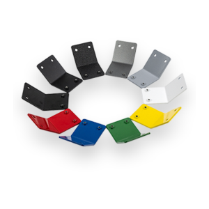
6061 can be anodized, bead blasted, powder coated, or tumbled for a polished look. These options are available through SendCutSend’s finishing services. Anodizing also enhances corrosion protection for outdoor or marine use.
6061-T6’s combination of strength, corrosion resistance, and machinability makes it suitable for a wide range of industries and end uses:
If your project requires strength, good machinability, and a clean finish — all without the corrosion concerns of 2xxx series alloys — 6061 is often the best overall choice.
6061-T6 aluminum is the workhorse of modern fabrication. It’s strong, corrosion-resistant, and easy to machine or weld. It’s less prone to corrosion than 2024, easier to bend than 7075, and maintains a consistent balance of performance and affordability. At SendCutSend, we laser cut 6061-T6 aluminum with ±.005” tolerance, offer fast 2–4-day lead times, and provide optional finishing services to take your parts from concept to production-ready. Whether you’re building a custom bracket, structural frame, or precision enclosure, 6061 aluminum delivers the reliability and versatility that engineers and makers rely on every day.