Have you ever thought about designing custom laser cut parts? Maybe you should.
Picture it: you have a project in mind and you need a specific part to make it successful. You’ve scrolled through 10s or 100s of braces, brackets, and plates online, and you’ve wandered miles of aisles in your local hardware store. You want to build something, hang something, or solve a unique problem using a perfectly sized item. Nothing you’ve seen is exactly right.
If this experience is at all familiar, you might be a designer.
This three-part series will show you how to get started with free 2D or 3D design software, create a file, and place an order at sendcutsend.com. Depending on the services your project requires, you could have custom laser cut parts headed your way within days.
Let’s get started!
Other guides in this series:
Forget the Hardware Store – Design Custom Bent Sheet Metal Parts Instead
Forget Etsy – Design Custom Laser Cut Gifts Instead
Free Software Options
While there are many free design software options out there, we highly recommend Autodesk Fusion and QCAD for beginners. Check out our full list of recommended software here: Recommended Software for Laser Cutting
3D Design: Autodesk Fusion
Autodesk Fusion has both paid and free, personal use licenses. If you’re just getting started, the personal use option is a great way to learn 3D design. We especially recommend Fusion if you need sheet metal bending services. Once Fusion is set up properly, the sheet metal tools will automatically calculate the dimensions needed in your flat part to get the final dimensions desired for your bent part.
2D Design: QCAD
QCAD is one of our most suggested programs due to its simplicity and usefulness. When it comes to designing simple flat parts, QCAD gets the job done quickly and saves 2D vector files in SendCutSend’s preferred file formats (DXF and DWG) natively. Even if you don’t end up preferring QCAD for design work, it’s great for double-checking 2D files before placing an order.
After installing the Professional Trial version for your operating system, check out Getting Set Up with QCAD for how to remove the Professional Trial add-on so you can use the free Community Edition without interruption.
2D Design: Inkscape
Inkscape is the best free software choice for decorative projects. We don’t recommend this program if your project needs a high level of precision (for example, you need bending, tapping, countersinking, or hardware services.) CAD programs like Fusion and QCAD are ideal for any mechanical parts.
However if you want to create something artistic with a lot of irregular contours, Inkscape can export a better quality file for that type of geometry.
Please note, Inkscape will not be covered in this guide. For an intro course on designing parts in Inkscape, check out Forget Etsy – Design Custom Laser Cut Gifts Instead.
Designing Your Parts
Software installed? We’re almost ready to go!
First: Design Guidelines
An understanding of SendCutSend’s design guidelines should factor into the design process at a fundamental level so you don’t end up needing to revise or redraw your designs to accommodate production or material limitations.
For an efficient design process and smooth order experience, confirm the following before you start:
- Which material you want the part cut from
- Design considerations for that material
- Design considerations for that material
- How that material is going to be cut
- Design considerations for that cut process
- Which, if any, additional services the part will need
- Design considerations for those services
Material Choice
The best material for your part will depend on the needs for your project. To help with the decision, SendCutSend has a Material Selection Guide and many material articles discussing qualities and applications for the materials we offer.
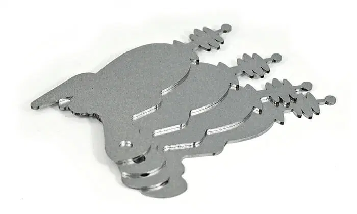
You can also compare the part you need to parts that are commercially available. For example, straps and braces are often made of galvanized steel due to the material’s strength and corrosion resistance. SendCutSend carries three thicknesses of laser cut G90 galvanized steel if that is the material you choose!
If you decide upon a different material, just keep any potential for oxidation in mind. Mild steel will rust over time if it is not protected, so you may want to consider adding our plating or powder coating services.
Design Considerations
For the purpose of this article, we’ll use 0.059” G90 galvanized steel for these parts.
To see all design considerations for any material, navigate to SendCutSend’s Materials Library and locate the material.
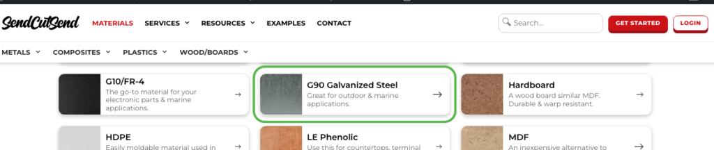
Then click to visit the material page, and scroll down to find the Material Details.
Select the thickness you need.

Here you can see that 0.059” G90 steel will be cut via fiber laser, so you’ll need to refer to the Laser Cutting Design Guidelines.
The material’s cut and thickness tolerances are also listed here. These are most important for parts that will require a high level of precision. Check out our explainers for cut tolerance and material thickness tolerance for more information.
If you scroll further down, you’ll come to the Design Considerations. Here you’ll find the critical specifications for cutting and other services offered for the material.

For cutting, the minimum hole and bridging/webbing sizes must be observed for successful parts. We have a guide on how to measure these specs here: How to Measure Cut Geometry Specifications Using QCAD. Although written for QCAD users, it is helpful for anyone who wants to know more about how SendCutSend defines cut geometry minimums.
For bending, scroll down further to find those specifications. We’ll touch on these later when designing a brace. We have an article covering essential bending considerations here: Design Considerations When Planning Sheet Metal Bends
To summarize the critical design constraints for 0.059” / 1.50mm G90 galvanized steel:
- The part cannot be smaller than 0.250” x 0.375” / 6.35mm x 9.525mm
- The overall part size cannot exceed 44” x 30” / 1117.6mm x 762mm
- Hole diameters cannot be smaller than 0.022” / 0.559mm
- Material bridging/webbing width between non-circular cutouts must be at least 0.030” / 0.762mm
- Bridging/webbing between circular holes and adjacent edges must be at least 0.020” / 0.508mm
Designing a Strap
Let’s say you need a metal strap to join two objects together in your project. Designing a custom laser cut part for the job is quite doable in free software programs. Here, we’ll create a rectangular strap with 4 holes to demonstrate how.
Fusion Process (3D)
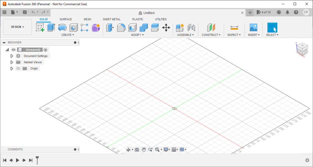
When you open Autodesk Fusion, it will default to showing the Design workspace in Solid mode.
1. Set Default Units
Before starting your design, set your preferences to your preferred unit of measurement – metric or Imperial. Files uploaded to SendCutSend’s website must be in either inches or millimeters. We cannot accept designs in centimeters (Fusion’s default unit).
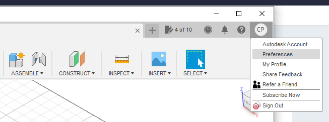
To update this, click the icon at the top right, then select Preferences.
Then, under Default Units, choose Design. At the drop-down menu choose either millimeters or inches and click OK.
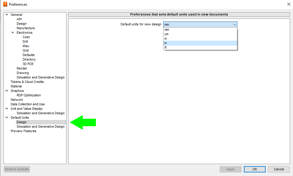
For the purposes of this example, we’ll leave the units in millimeters.
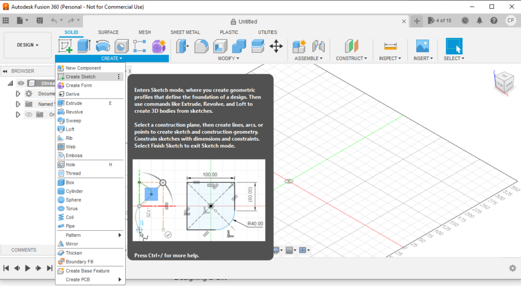
2. Creating a Sketch
Next, click CREATE to expand the drop-down menu and then click Create Sketch.
You’ll be prompted to select a plane or planar face to work from. Choose the flat plane, not one of the vertical planes.
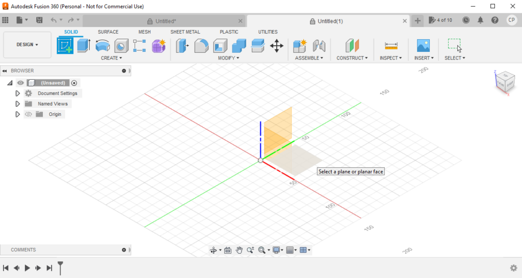
When you click the flat bottom plane, you’ll be brought to the top-down graph paper view in Sketch mode.
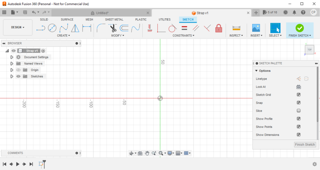
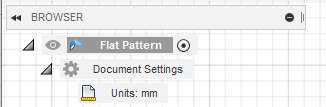
In the Document Settings, you should see that the drawing units are set to your default units.
You can also change the units for this drawing here if desired.
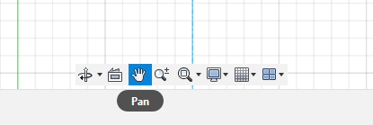
You can use the Pan tool to move around the work space if needed.
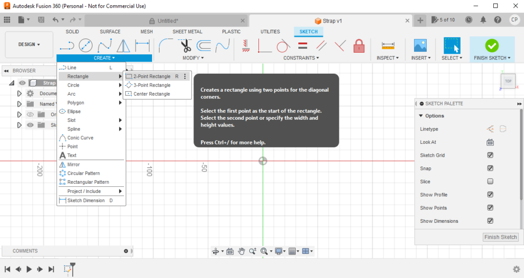
3. Draw a Rectangle
From here, click CREATE to access the drop-down menu, then hover over Rectangle. In this example we’ll choose 2-Point Rectangle (keyboard shortcut R).
Using the 2-Point Rectangle tool, first click the starting point for your rectangle. It is best practice to click the origin point (the point where the red and green lines intersect).
Then, move the cursor to determine the second point’s location and the overall size of your rectangle.
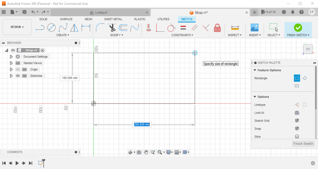
It’s best practice to start typing and enter the exact dimensions you need for your rectangle.
When one side is set, press tab to enter the dimension for the other side.
We’ll make this rectangle 245mm x 127mm.
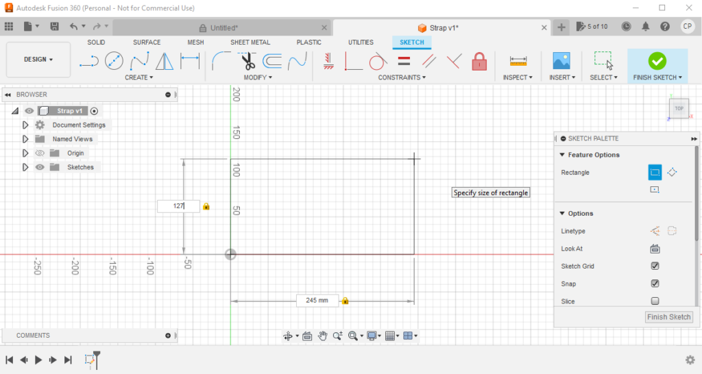
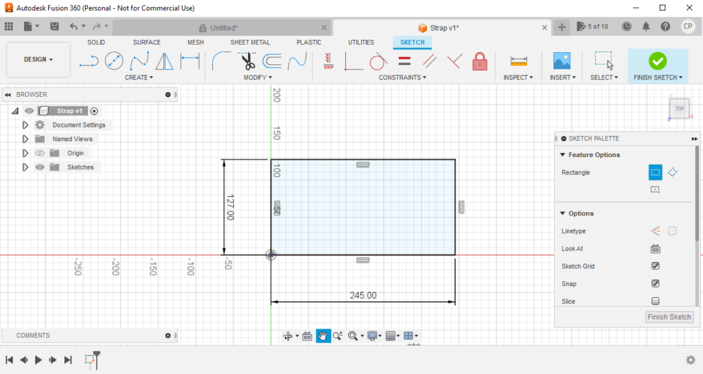
Once the size is correct, click a second time to finalize the shape.
If you see a black border and dimensions, this means you have a fully defined shape which is best practice in Autodesk Fusion.
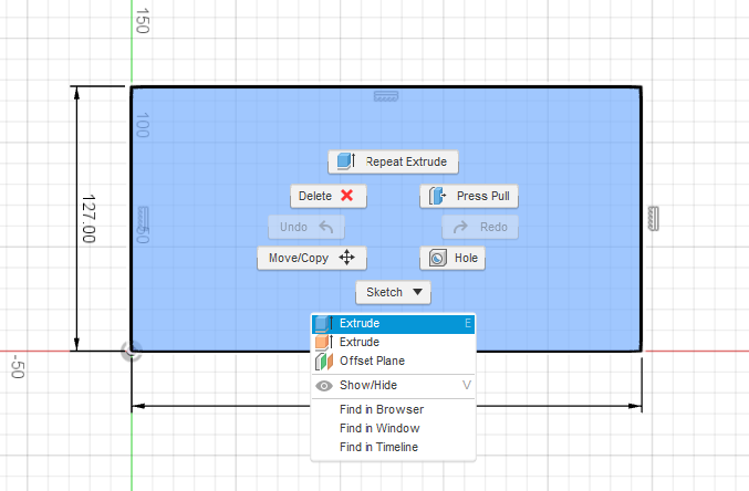
4. Extrude the Shape
Next, we’ll extrude the rectangle to make it into a 3D shape. Extruding isn’t strictly necessary when designing a flat part but Fusion’s design tools are optimized for working in 3D, so this will make next steps easier.
To do this, select the face of the part, right click, and select Extrude or press the keyboard shortcut E.
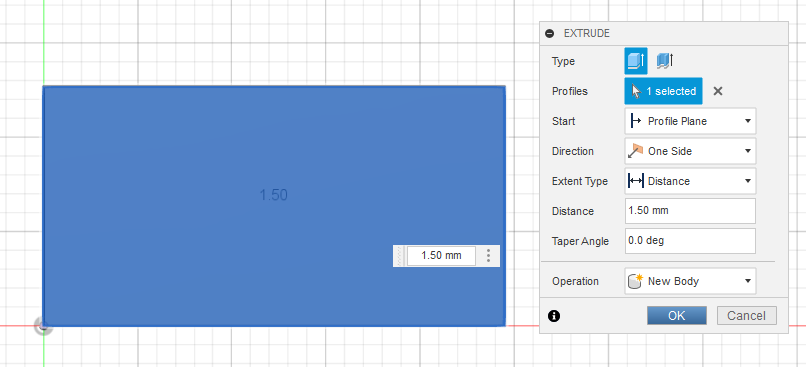
This will open the EXTRUDE window. Here, enter the Distance to extrude which in this case should be the material thickness (1.5mm). Then click OK.
The shape will turn gray and you’ll be under the Solid tab since you’re no longer working on the sketch.
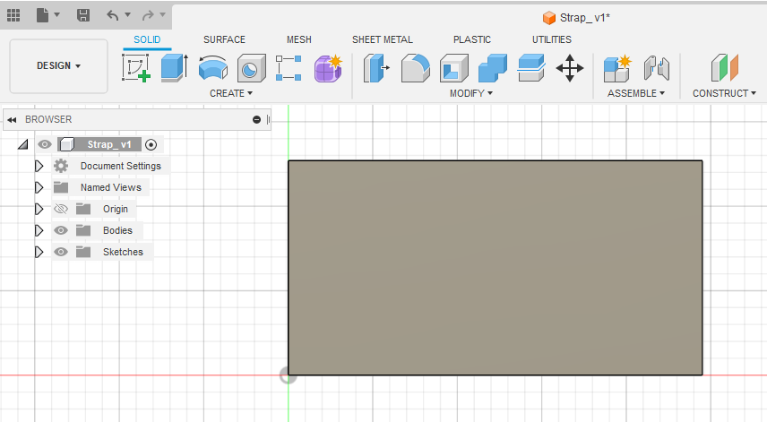
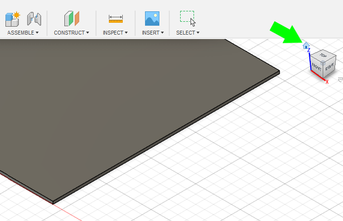
If you click the Home button at the top right, you’ll be able to quickly see the 3D view of the shape.
Note: you can also extrude a part using the Flange tool. Learn how to do this here.
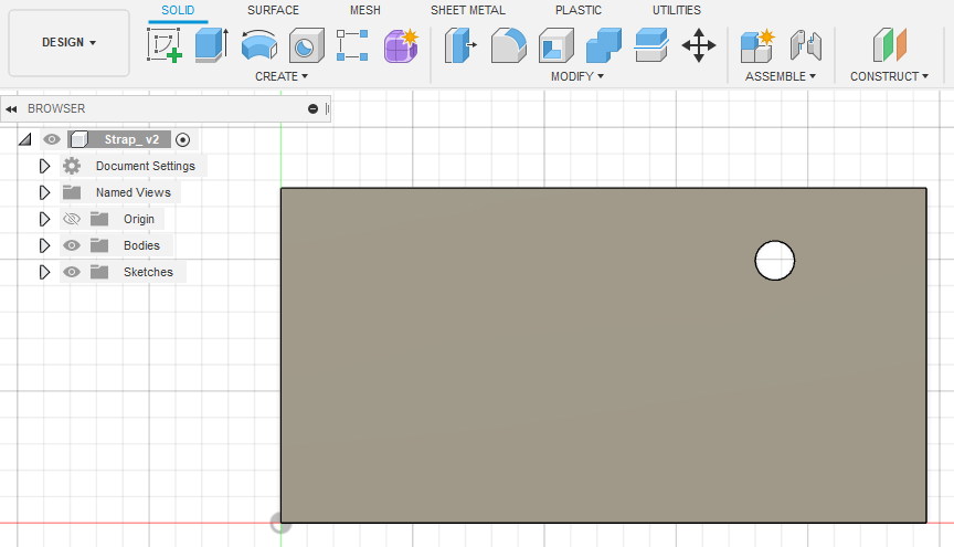
5. Create and Place Holes Where Needed
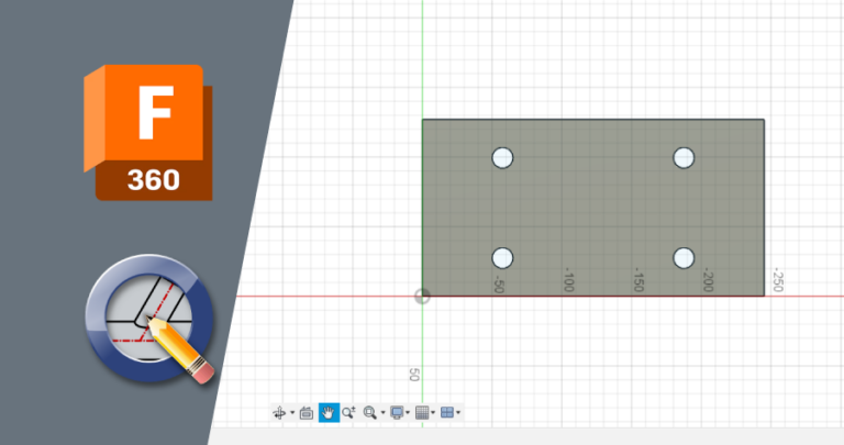
This will depend entirely on the needs of your project. For the purpose of this example, we’ll create four 15mm holes. We’ll place them 20mm away from the top and bottom edges, and 50mm away from the left and right edges. This ensures that the part meets the cut geometry specifications for the 1.50mm G90 material.
Fusion’s Hole tool (keyboard shortcut H) makes this easy to do!
After returning to the top-down view in the workspace, press H or access the Hole tool from the main toolbar or CREATE dropdown menu.
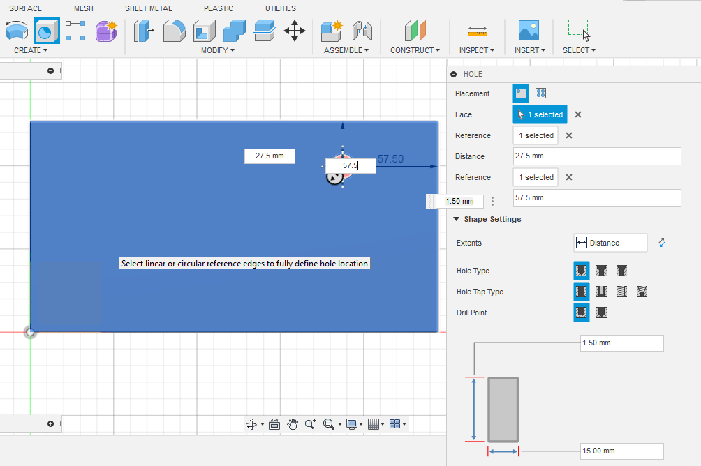
This will open the HOLE tool window.
- For Placement, we’ll use At Point (Single Hole).
- Select the part face, and ensure the hole depth is set to at least the material thickness.
- Then, click the top edge and type in the desired edge-of-hole to edge-of-part distance + the hole radius, since Reference distance is set from the center of each hole in the Hole tool.
- Therefore we’ll offset holes from the top and bottom edges to 20mm + 7.5mm = 27.5mm.
- We’ll offset holes from the left and right edges to 50mm + 7.5mm = 57.5mm.
- Extents should be set to Distance
- The Hole Type, Hole Tap Type, and Drill Point can all be Simple, Simple, and Flat
- Set the hole diameter at the bottom
When the settings are correct, press Enter or click OK to finalize the hole.
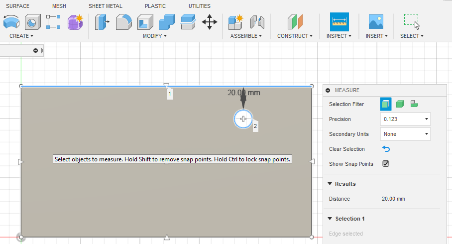
If you want to check your work, you can use the Measure tool (keyboard shortcut i). When measuring the distance between two objects, click the first object and then the second to see the measurement.
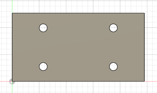
We’ll repeat the Hole tool process so there are a total of 4 holes.
6. Design Spec Recap
Before exporting, double-check that the design meets all relevant specifications.
- Overall part size within material limits?
- Holes and cutouts large enough?
- Bridging/webbing wide enough?
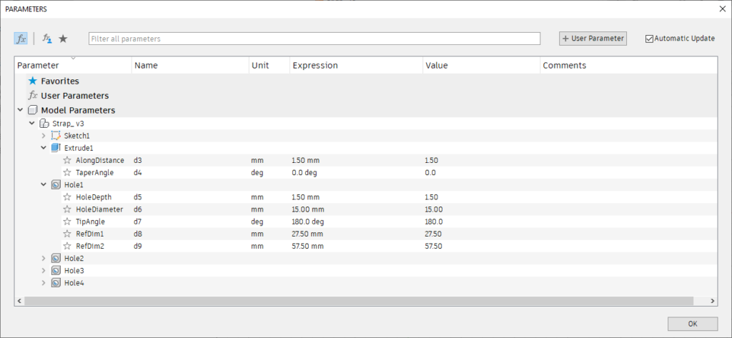
If you need to change the dimensions of any geometry that you entered specific dimensions for, you can do so by clicking MODIFY to expand the dropdown menu and selecting Change Parameters.
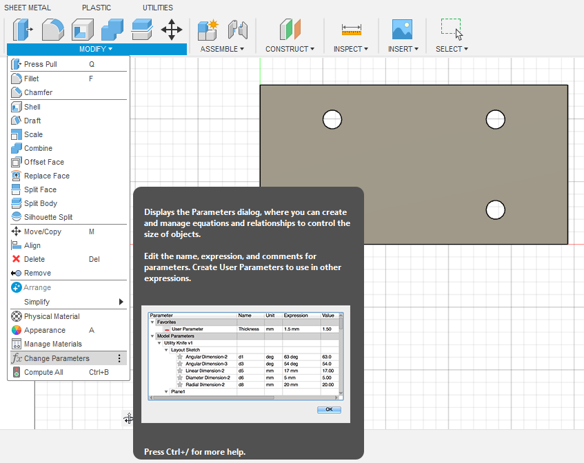
This will open the Parameters window. Here, you can adjust the dimensions under Model Parameters. Change the dimension as needed in the Expression column, then click OK.
If you did not type in the dimensions when you drew your shapes, you can adjust their size manually using your cursor/Select. Manually drawn shapes will not have the dimensions indicated. However, this is not ideal! It’s best to type in your dimensions so they are exactly right and easy to precisely adjust later if needed.
When the design is ready, it’s time to export!
7. Export DXF from Fusion
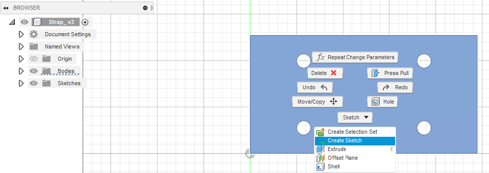
To export the flat cut pattern we need from Fusion, right click on the face of your part and click Create Sketch.
This will create a new sketch under Sketches on the left. Find the new sketch and right click on its name under the Sketches dropdown. Then click Save As DXF.
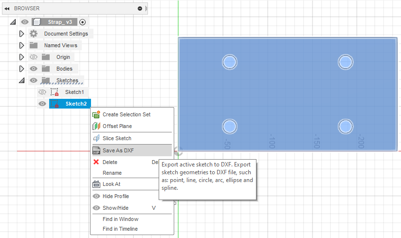
This will prompt the Save As DXF dialogue. Save the file, and you’ll have a flat, laser-ready DXF!
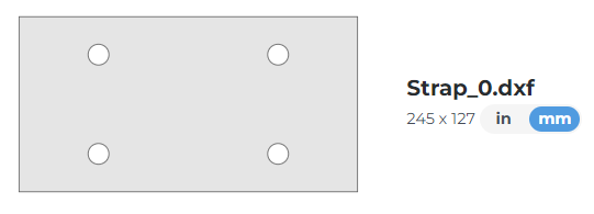
8. Upload to SCS Website
When the DXF is uploaded to SendCutSend’s website, the part preview should look just like your sketch and show the correct overall dimensions.
QCAD Process (2D)
Unsurprisingly, using a 2D program can be the quickest way to whip up flat parts! Best of all QCAD edits DXF files natively so there’s no export process per say – you just click Save.
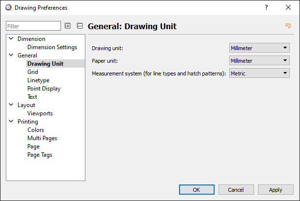
1. Set Drawing Units
Before starting, again you’ll want to ensure the drawing units are set to either inches or millimeters.
Navigate to Edit > Drawing Preferences or press Ctrl+I to update the Drawing Unit settings if needed.
Click OK.
2. Draw a Rectangle
Then, use the Rectangle With Size tool (keyboard shortcut RS) to draw the rectangle.
You can access the tool from the Shape Tools menu (WH) or from the toolbar (Draw > Shape).
For this part, we simply need to input the correct width and height. We’ll leave the Create polyline, fill, and radius boxes unchecked.
Then hover your cursor over the workspace, and click to place the shape.
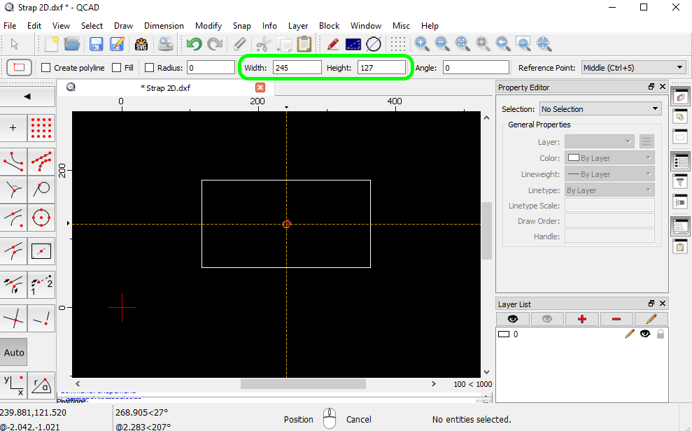
Press Escape to exit the tool.
3. Add Temporary Guide Lines
To ensure the circles we’ll draw are placed correctly, we’ll add temporary guide lines that we will delete later.
The Offset (with Distance) tool (keyboard shortcut OF) allows you to do this quickly. You can access the Offset tool through the Modification Tools menu (WM) or by navigating to the toolbar Modify > Offset (with Distance).
We’ll need to set the offset distances to be the hole edge to part edge distance desired + hole radius, because we’ll want the circle centers to snap to the guide line intersections.
Therefore we’ll offset the top and bottom edges to 20mm + 7.5mm = 27.5mm.
We’ll offset the left and right edges to 50mm + 7.5mm = 57.5mm.
Set the distance and hover your cursor over the edges you want to offset from.
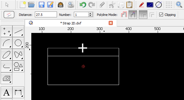
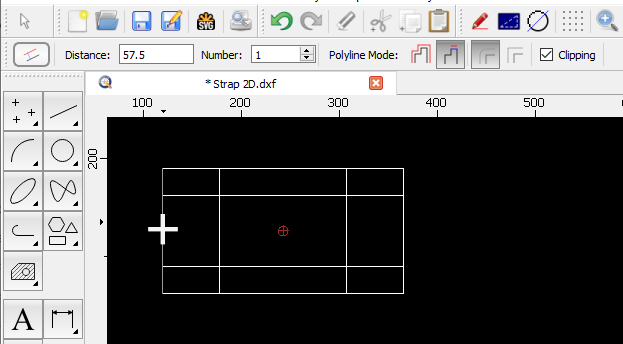
Once the guide lines are drawn, the holes can be added.
4. Add Holes
The simplest way to draw holes at the exact size you need is by using the Center, Diameter (keyboard shortcut CA) tool. This will allow you to specify the desired diameter and place circles via the centerpoint.
You can access this through the Circle Tools menu (keyboard shortcut WC) or by navigating to Draw > Circle at the toolbar.
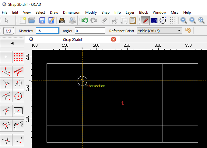
Once the diameter is set, drop a circle at the intersection of each guide line. You may need to update the Auto Snap preferences in QCAD to snap to intersecting paths. We have instructions on how to do this here: Customizing Application Preferences in QCAD
You can also turn this on by pressing the keyboard shortcut SI (Snap, Intersection) or navigating to Snap > Intersection from the toolbar.
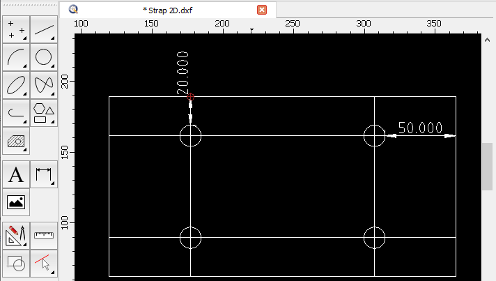
After all circles are drawn, you can check your work if desired by measuring with the Aligned Dimension tool (keyboard shortcut DA).
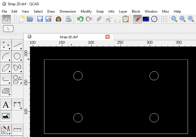
5. Delete Guide Lines
When you’re happy with the design, delete the dimensions and guide lines.
6. Design Spec Recap
Before exporting, double check that the design meets all relevant specifications.
- Overall part size within material limits?
- Holes and cutouts large enough?
- Bridging/webbing wide enough?
7. Save the DXF
When the design meets all guidelines, save your DXF file and you’re done!
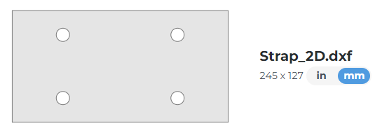
8. Upload to SCS Website
When the DXF is uploaded to SendCutSend’s website, the part preview should look exactly the same and show the correct dimensions.
Conclusion
There you have it – the fundamentals of designing custom laser cut parts! At SendCutSend we believe you can create solutions to any problem – no need to compromise with mass-produced one-size-fits-all hardware. Just design using our guidelines and upload your files. We’ll bring your ideas to life!
For more tips on working in Autodesk Fusion or QCAD, see our Fusion and QCAD archives.
It’s been a good time in the flatlands, and now it’s time to get bent! Move into a new dimension with our next guide: Forget the Hardware Store – Design Custom Bent Sheet Metal Parts Instead
Want to know what happens after you place an order? Learn about SendCutSend’s processing times and shipping speeds.
