Autodesk Fusion is great for modeling, rendering, and fitting your 3D designs together. When you upload your DXF to our instant pricing tool, however, we need it to be a 2D file. Watch the video or follow along with the transcript below to see how to export a sketch to DXF from Autodesk Fusion.
Be sure to export your designs in either millimeters or inch units; we have guidance on how to change units in Fusion here.
Creating a Sketch in Autodesk Fusion
DXF files can only be made from sketches. Depending on how you designed your file, you may or may not have sketches attached. You can easily create a sketch if you don’t, or just create a new one for this process. Sometimes if you’ve made modifications, they may not be reflected on your original sketch so a new sketch can be beneficial.
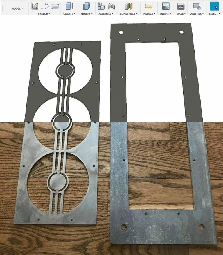
Find a flat part that you want to export to be cut. In this example, we have a shifter assembly for a custom car build. We’ll be taking the base plate to export as a 2D file to DXF for laser cutting.
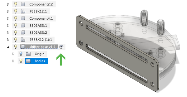
In order to create a sketch, you need to have only that component selected.
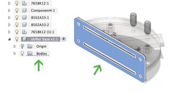
Now you’ll open up our component. You can see here that this component has no sketches attached. Select the body and face that you want to export.
With the face selected, hit the “P” key on your keyboard to access the Project tool. You’ll be asked to select a plane or geometry. Select the main face geometry. Click “Ok”.
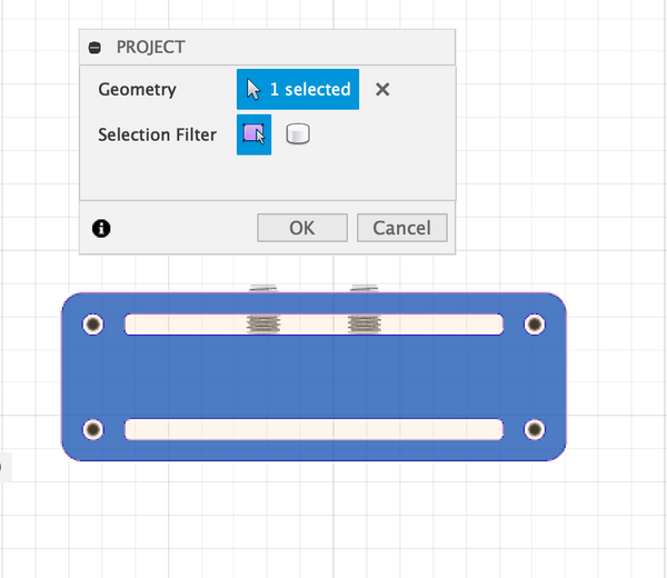
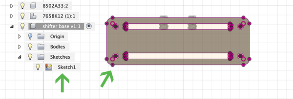
You’ll now see a sketch attached to your body. You’ll also see purple handles around the selected face.
Export a Sketch to DXF from Autodesk Fusion
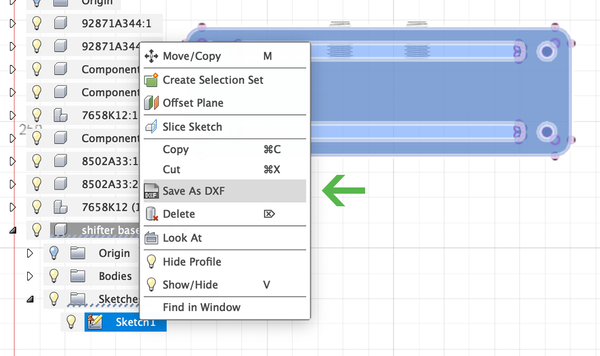
Now you’re ready to export the sketch to DXF. Right click your sketch and select “Save as DXF”. You’ll be prompted to name the file and export location.
Final Notes on Exporting from Autodesk Fusion
We strongly recommend that you reopen your DXF in a new Autodesk Fusion file, or in Adobe Illustrator to verify that everything looks the way it should. Check it against our Pre-Flight Checklist here:
- File is in a two-dimensional vector format file.
- All holes and cutouts are at least 50% material thickness and adequately spaced away from the die line (no less than .063″ for waterjet cut parts)
- Bend lines are shown using the correct indicator for your program
- File is built at a 1:1 scale, preferably in inch-units
- All objects are on the same layer
- All stray points, duplicate lines, empty objects and text areas have been removed
- No shapes have open contours
- All shapes have been united, combined or merged
- All text has been converted to outlines or paths
- Cut-out text (reversed text) has bridges or has been stencilized
After you’ve checked your DXF, upload it to our instant pricing tool and get ready to receive your parts in just a couple of days!
We’re here to help
If you have any additional questions about how to export a sketch to DXF from Autodesk Fusion, check out our other Autodesk Fusion blog posts or reach out to our awesome support team. We want to help you make your files successful so we can provide you with the best and quickest laser cut parts.
