If you’ve ever designed parts for 3D printing, but want to explore what possible with 2D laser cutting and CNC machining, you’re in the right place. Most popular design programs have a 2D export option, but each one is a little unique and may require a few steps to get us the best possible file.
With a little attention to detail, your 3D designs can become perfect 2D files to use in laser cutting and 2D CNC machining.
Start with the Correct Software
Using the right software is the most important part of the DFM (Design for Manufacturing) process. Using software that is designed for 3D printers or 3D animation may not be optimized for 2D laser cutting or CNC machining.
Here’s a few of our favorite programs to use for 2D laser cutting and CNC machining:
Fusion
Free for personal use – Very powerful design software that can output perfect DXF files for us, if you know a couple of steps to take.
Exporting to DXF From Fusion
QCAD
It’s Free! – We love QCAD for its simplicity, cost (free for personal use), and it’s well documented. (tutorial soon)

SolidWorks
This is the industry standard. If you are good at SolidWorks, you’ll never be unemployed. Expensive, but a reduced cost option is available with an EAA membership or if you are a student.
Some 3D-centric programs offer an option for 2D exporting, but they do not define 2D shapes accurately or efficiently. If you’re working in the following programs, your 2D vector files will likely not be optimized for laser cutting, and are not supported by our process:
- TinkerCad
- Rhino
- SketchUp
- VCarve
Send Us the Correct File Type
The software you use will determine the file type that you send to us. The file types we accept are:
DXF – Exported from a sketch in SolidWorks or Fusion. Save-as from QCAD or other popular 2D CAD programs
DWG – Save-as from AutoCad, Revit, ArchiCAD
AI – Save-as from Adobe Illustrator only. If your program has an option to export as an Illustrator file, but it’s not Illustrator, try an .eps option instead.
EPS – Save-as from Adobe Illustrator or Corel Draw
Don’t Use Conversion Apps
If your software doesn’t save-as or export the common file types we accept, that’s a sign that there will be problems with the file you send us. If you attempt to convert a file from one form to another using an online converter, app or plugin, weird things can happen. In most cases, the file will not be useable.
Similar to human language, the more you process a file through a digital translator, the less legible it will get (Google translate from English to Spanish then back to English to see what I mean!).
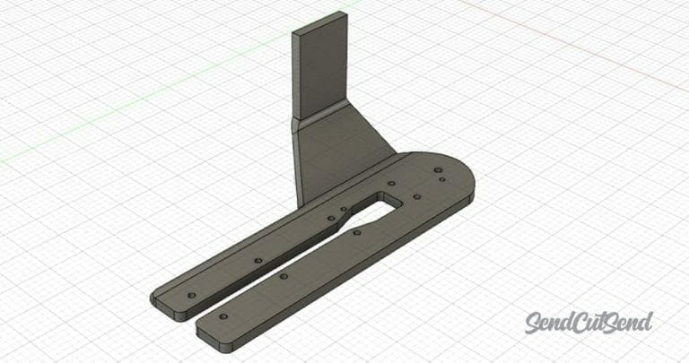
Fusion and SolidWorks: Focus on the Sketch
In Fusion or SolidWorks, the first thing you do to create your part is make a sketch. For modeling purposes, you’ll go on to extrude, revolve or loft that sketch to make a fully formed shape. When you’re designing for laser cutting though, the initial sketch might be all you need!
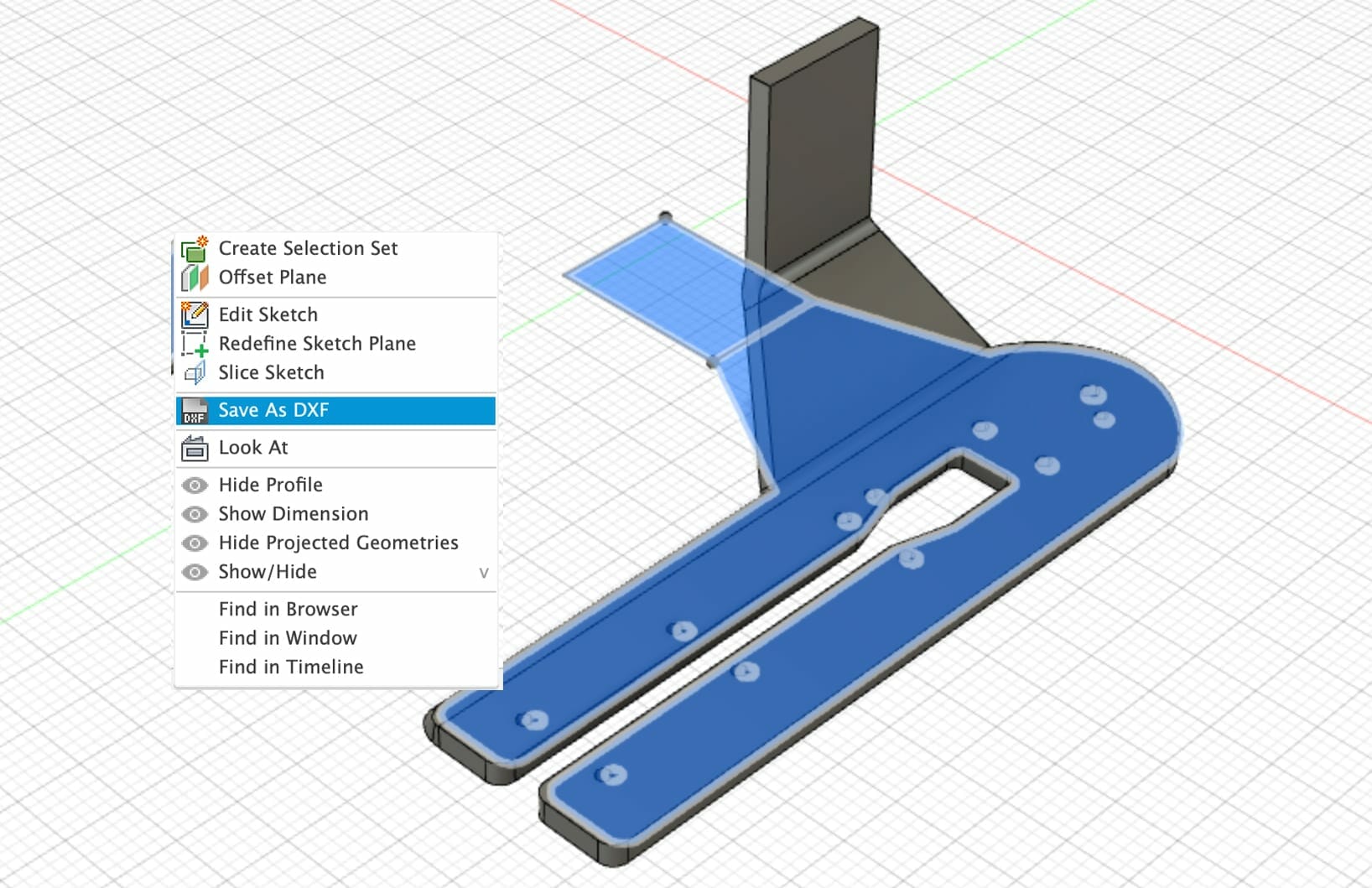
Learn more about how to create a DXF from a sketch in Fusion.
Adobe Illustrator – Just Click save!
Although Adobe Illustrator doesn’t support 3D design, it’s still a great tool for creating 2D parts. If you designed your file in Illustrator, send us the original .AI file. Please do not export as a DXF, we have a special conversion process that we use to retain the arcs and curves in your design accurately.
Here’s a couple things to look out for to make the process easier:
- Remove guides
- Remove hidden layers
- Unlock all objects
- Remove stray points
- Use a single artboard
Designing for Laser Cutting in Illustrator
Check Your Export
If you view your DXF file in software like QCAD and it looks like there are more nodes than necessary, that’s a sign that your software didn’t export the DXF correctly. We might be able to cut the parts for you, but the cut quality will be reduced.
The laser reads simple lines and shapes (we call the shapes “geometry”) to determine the cutting path. All the geometry is defined by “nodes.” Nodes are like a connect-the-dots game, and the laser will happily go from one node to the next. Each node contains a set of directions, and can instruct the laser to go straight to another node or arc to another node.
If you’re cutting a circle or hole in your design, there will be four nodes that define 4 small arcs that make up the circle. The laser can read those instructions effortlessly, and the hole will cut nice and smooth. If your design isn’t exported correctly, instead of smooth arcs, you’ll get hundreds (or thousands) of tiny, straight-line segments and a ton of nodes. These extra nodes will result in rough or jagged edges on your part.
You’re All Set!
Getting the hang of it? For tips on getting perfect exports every time in our supported software, we’ve got some handy tutorials here. Still not convinced why we’re so picky? Here’s why we require vector files for laser cutting.


