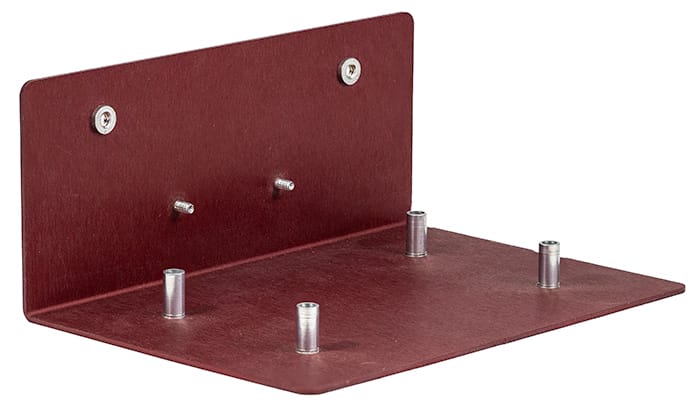
Hardware insertion helps streamline your design-to-build process. SendCutSend’s hardware offers a fast, affordable solution to connecting your metal parts.
Extensive catalog of PEM hardware
More than 200 nuts, standoffs, and studs in imperial and metric sizes.
Automatic hole resizing
We resize the holes in your design to fit the hardware you choose.
Faster production
Our in-house hardware insertion only adds 1-2 days to production time.
“I used their insertion products to add flush mount studs to some parts and they were all installed perfectly and they’ve held up to some serious repeated abuse.
Matthew Fuller
Available materials for Hardware Insertion
We currently offer seven materials in a variety of thicknesses for hardware installation:
One step to a finished part Built to take abuse Looks as good as it performs
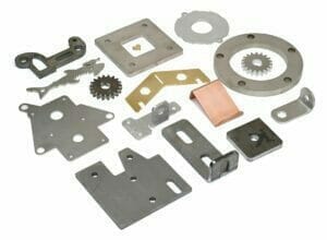
A variety of high-quality hardware options to suit every need
Hardware provides options when there is little to no access to the backside of a part after installation or in place of tapping in thin or soft materials. We are proud to offer a variety of PEM(R) fasteners.
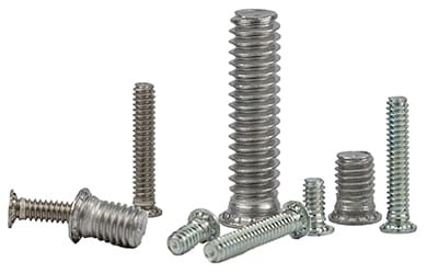
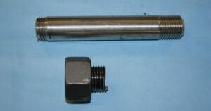
Studs
Self-clinching studs are designed to be a permanent fastener in your assembly made to withstand high torque, stress and weight in a variety of applications
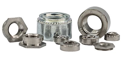
Nuts
Press fit nuts are internally threaded with a knurled outer diameter providing a lightweight, simple option for parts that are too thin to be tapped. Choose from standard or flush.
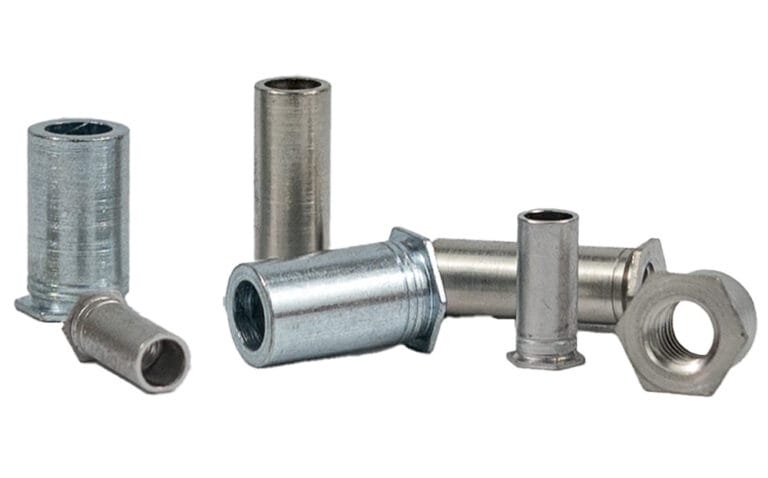
Standoffs
Press fit standoffs provide a secure, threaded fasting with uniform spacing between parts.
Following a few basic design guidelines will help ensure your parts pass SendCutSend review.
Min & max part sizes for hardware insertion
All parts with hardware installation need to meet certain size requirements to be manufactured correctly:
Min part size (flat)
1″ x 1.5″
Max part size (flat)
36″ x 46″
Max hole size
4″ (holes will be automatically resized
These are general size requirements. Check the Hardware Catalog for specifications on each hardware type before uploading your file.
Hole sizing
When you select a hole for hardware installation, we automatically resize the hole to the required size based on the hardware you choose. The required size is listed as hole size in sheet (H) in the hardware catalog for each hardware SKU.
Because mount holes will be resized, verify there’s adequate clearance to other features and edges. Measure from the center of the mount hole to the edge of adjacent cut features.
Specifications in the hardware catalog
H = Hole size in sheet (+0.003″/–0.000″) J = Bend allowance (find with Bend Calculator) K = Minimum distance from center of hole to cut edge N = Minimum distance from center of hole to edge of bend allowance area (J) M = Minimum distance from hole center to hole center for two of the same hardware SKU P = Minimum distance from hole center to hole center for two different hardware SKUs
Hardware-to-hardware distance
The minimum distance between two of the same hardware SKU is listed as spec M in the hardware catalog. For two different hardware SKUs, calculate the minimum distance manually: the minimum distance hole C/L to edge (K) for either hardware should not overlap the hole size in sheet (H) of the other. In the example below, the shaded areas should never overlap any cut edges.
Note: Hardware that is the same size but a different type or SKU can have different specifications. For example, an 8-32 nut and an 8-32 standoff require different mount hole sizes and spacing.
Hardware-to-bend distance
Hardware holes must be far enough away from bend allowance areas to prevent interference.
Confirm the bend allowance for your flange using the Bend Calculator (input material thickness and bend angle, find under Advanced details).
Find the minimum distance hole C/L to edge or bend area (N) in the hardware catalog for your hardware SKU.
Measure from the center of the hardware mount hole to the edge of the bend allowance area in your design.
You can also measure from the center of the bend to the center of the hardware hole. Calculate that minimum by adding bend allowance/2 + minimum distance hole C/L to edge or bend (N) for the hardware SKU.
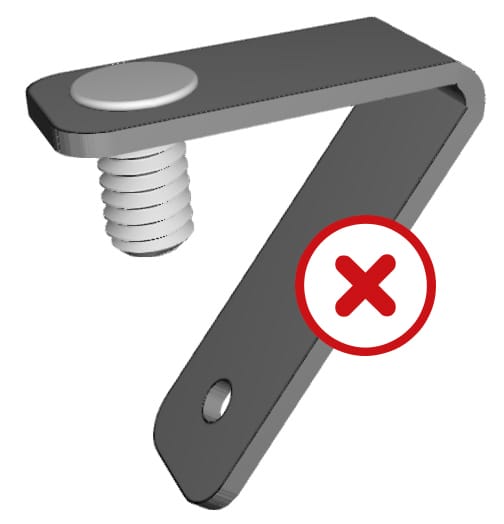
No hardware on acute bends Hardware installation isn’t available on parts with acute bends. Contact support if you have questions about your design.
Hardware insertion options for sheet metal parts
We offer three types of PEM® hardware: nuts, standoffs, and studs. Each type has a specific load direction it’s designed for, orienting hardware against the load direction can cause it to fail or pop out of the part. Use the diagrams below to confirm the correct direction for each type, then set the install face in the app.
Press fit nuts
Press fit nuts install with the load direction pulling the nut into the part, never away from it.
Press fit standoffs
Press fit standoffs install with the load direction pulling away from the part. Loading them toward the part can cause failure.
Self-clinching studs
Studs install with the threaded shaft protruding from the part. The load direction should pull along the shaft, away from the head.
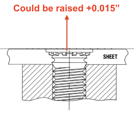
Flush head standoffs and studs
Our flush standoffs and studs are technically flush, but may be raised .015″ depending on material selection. Load direction follows the same rules as standard standoffs and studs.
What to expect with hardware inserted parts
Visible tooling marks at the installation point
Hardware is installed after anodizing and plating
Hardware is installed before powder coating, hardware will be capped/plugged before coating
Standoffs and studs may sit raised .015″ depending on material selection
Beware scratching or marking on anodized or plated parts
Hardware should only be used for its intended purpose, shearing, splitting, or warping may occur otherwise
Improper use of hardware can result in failure
Additional hardware insertion resources
If you’re designing parts for hardware insertion, these resources may help:
First time I've used Send Cut Send, they exceeded my expectations. I got a fully laser cut part out of 1/2" thick steel for nearly the price of just purchasing the material.
Posted on
Dale Parent
May 4, 2026.
sent cut and sent very fast, nice packaging of the parts. I have a ready recommended to others.
Posted on
Chris Hutchinson
May 4, 2026.
I needed some specific shapes of acrylic cut for Windows for a 3D printing enclosure and even though there was something like 8 or 10 pieces in there, it was under 40 bucks and I think it took something like a week to get to me after ordering. Some of the details are a little fuzzy but I was ecstatic with the result and would 100% recommend.
Posted on
leemach1
May 4, 2026.
Excelent 1st time use of this company. Couldn't believe how easy it was to generate, and how fast the turn-around was! Thanks
Posted on
R L
May 3, 2026.
I'll just say that the team at SendCutSend absolutely came through for me to build additional panels needed after a change order and managed to get them to me in a very tight schedule. Everything arrived perfect! packaged well in protective coverings. Couldn't recommend them enough.
Posted on
Oscar Weir
May 3, 2026.
Awesome service, super quick turn around, and perfect results. Thanks SCS!
Posted on
lee Yates
May 3, 2026.
Awesome service and fast shipping as always. Parts are always spot on from the files we send
Posted on
Conrad Chin
May 3, 2026.
I discovered Send Cut Send when I needed a custom speedometer harness for my motorcycle. The experience from start to finish was seamless. It was easy to upload my CAD file, and I really appreciate the quick and personal responses to my questions. Will use again!
Top Quality Store
Please note: Pricing examples on our website are provided as general estimates and may not always reflect current prices. While we strive to keep these examples accurate, uploading your file is the best way to see instant current pricing.
Start your first SendCutSend project today!
Upload your CAD design, or try one of our customizable part templates to get instant pricing on your custom laser cut parts. All delivered to your door in a matter of days.