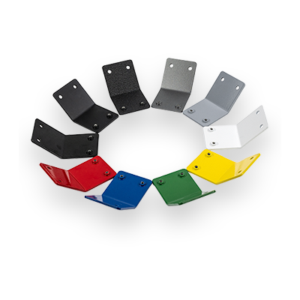
10 Thicknesses
Production Time

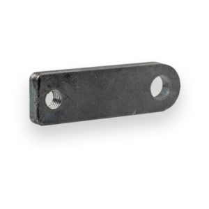
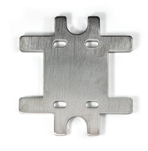
Laser cut, +/- .005" tolerance
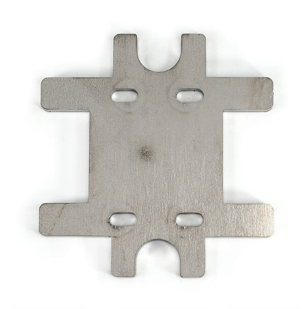
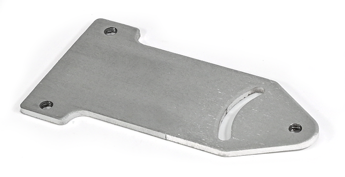
Thicknesses greater than .125″ will have a factory #1 mill finish. When not deburred, the appearance will be dull with visible mill scaling.
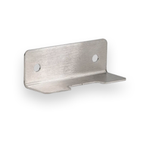
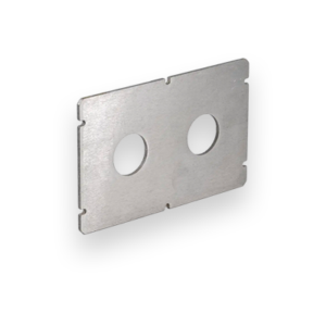
Weldable, formable, and easy to work with, 304 stainless is our first choice for projects that require massive strength and durability.
Laser cut 304 stainless steel is oxidation resistant, making it easy to sanitize and maintain. This particular feature makes 304 stainless steel the go-to grade for many food service applications, from countertops to cookware.
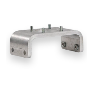
Fusion welding performance for 304 stainless steel is excellent both with and without fillers so it’s a strong choice across projects that require welding. Heavily welded sections sometimes require additional treatments, such as annealing, but generally the material is simple to weld.
Ultimately, you can count on SendCutSend’s 304 stainless steel laser cutting services to meet your project’s needs and provide solid parts made to your specifications.
We guarantee awesome quality parts. If you’re not 100% happy, we’ll give you a refund or remake on the spot – no questions, no hassle.
This material is available in ten thickness options: .030″ (0.76mm), .048″ (1.22mm), .060″ (1.52mm), .074″ (1.88mm), .100″ (2.54mm), .125″ (3.18mm), .187″ (4.75mm), .250″ (6.35mm), .375″(9.53mm), .500″ (12.7mm).
SendCutSend cuts 304 Stainless Steel in a broad range of sizes and thicknesses. Instant quoting is available for parts as small as .25″ x .375″ and as large as 30″ x 44″. Larger parts, up to 30″ x 56″, can be ordered through a custom quote.
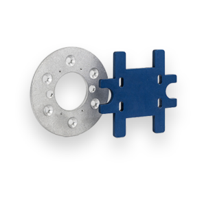
You can add the following services to your 304 Stainless Steel parts:
Bending, Deburring, Dimple Forming, Hardware Insertion, Powder Coating, Tapping, and Tumbling
We accept .ai, .dxf, .dwg, .eps, .stp, and .step
Customize one of our simple parts templates

304 stainless steel is one of the most widely used metals in the world, prized for its corrosion resistance, durability, and versatility in fabrication. At SendCutSend, 304 is one of our most popular stainless options for laser cutting, available in 10 thicknesses from .030″ up to .500″. If you’re designing parts for laser cutting and fabrication, understanding how 304 behaves will help you get better results on the first try. Below we’ve put together a deep dive into the most commonly asked questions about 304 stainless steel, optimized for both engineers and makers.
304 stainless steel is an austenitic chromium-nickel alloy that belongs to the 300-series of stainless steels. It’s considered the “workhorse” of stainless, making up over half of all stainless steel produced worldwide.
Want to compare? Check out our 316 stainless steel page for applications where chloride resistance is critical.
Yes 304 stainless is one of the best candidates for fiber laser cutting, the process SendCutSend uses.
At SendCutSend, we hold a cutting tolerance of ±.005″ on stainless steel, which makes it an excellent choice for parts requiring tight fitment. For more detail, see our laser cutting guidelines.
Stainless generally cuts cleanly, but a few issues can crop up if not optimized:
Bending 304 stainless steel is very doable, but it requires some planning compared to bending mild steel or aluminum. At SendCutSend, we bend 304 every day on our CNC press brakes, so here’s what you need to know when designing for stainless bends.
If you need superior corrosion resistance, consider our 316 stainless.
SendCutSend ships stainless steel parts with a mill finish by default, which is the raw, as-rolled finish from the mill. This finish is perfectly functional but may show light scratches or surface marks from handling. If your project calls for a cleaner or more decorative look, we offer several finishing options:
At SendCutSend, we hold ±.005″ cutting tolerance across stainless thicknesses up to 0.500″. For more detailed specs on each thickness, check the material specifications section of our catalog.
For all minimums and maximums, see our design guidelines.
At SendCutSend, standard lead time for stainless steel parts is 2–4 business days before shipping, regardless of thickness. Learn more about how we process parts in our instant quoting system.
For more demanding corrosion resistance, see 316 stainless.
Laser cutting is just the start. To save you time and keep your parts production-ready, SendCutSend offers several add-on services for 304 stainless steel:
DIY cutting is possible with the right equipment, but stainless is tough:
For most makers and engineers, outsourcing to SendCutSend is faster, more cost-effective, and higher quality than trying to cut 304 yourself.