Sheet metal hardware provides options when there is little to no access to the backside of a part after installation. It can also replace tapping, but what’s wrong with a tapped hole? How about a nut and bolt–or a tack weld for that matter?
The short answer is; nothing really, we put each of those to good use around here all the time. Typically, hardware is a better option than tapping in sheet metal due to the material thickness and the type of material. In most sheetmetal there is not enough thread engagement for proper use. Consider how long a tapped hole in 0.040” steel would hold a fastener (with self-clinching hardware, that same sheet metal can be safely used).
Perhaps you’d like to powder coat or anodize your part so welding isn’t an option.
In many design situations, it’s beneficial to have pre-mounted fasteners that don’t rotate, resist corrosion and won’t warp your part.
Sounds great, but with what? That’s what our sheet metal Hardware Insertion services are for. Let’s take a look at the process of designing around it and ordering your custom sheet metal designs in a few easy steps.
What Type of Hardware Does SendCutSend Offer?
Here at SendCutSend our hardware services offer over 100 different PEMⓇ nuts, studs and standoffs to suit your specific application.
From electrical panels, to airplane frames, PEMⓇ has been a leader in the “self-clinching hardware” sector for over 80 years. Since they’re corrosion and vibration resistant, PEM fasteners are used by 90% of top automakers, so even if you are building a car completely out of laser cut sheet metal, it should stay together no matter the driving environment.
The best part? Our Hardware Service has no minimum quantity and starts as low as $0.40 per hole so you don’t have to worry about breaking parts OR the bank.
How to Design for Sheet Metal Hardware?
Alright, you’re convinced that Hardware is going to take your design from good to great. First, you may want to familiarize yourself with the Hardware Guidelines which have lots of information on available materials (aluminum and steel), minimum and maximum parts sizes, and force diagrams for each fastener type. While you’re at it, take a look at the metal bending service guidelines as well, since these two services are often used together.
Now, let’s look at some real examples of how to use hardware. To begin, fire up your design software of choice (here are our top picks). Today we’ll be using SolidWorks, which makes Hardware implementation a snap with native PEM fastener integration, meaning a nut, stud, or standoff can be added to the assembly with a simple drag-and-drop.
Even if you’re not on team SolidWorks, whether using a 2D program like QCAD or another full-featured 3D software suite, fastener dimensioning and placement is quick and easy when you use the PEM Catalog to download a model of any fastener we offer from.
Let’s look at how to add nuts, studs, and standoffs accurately and easily by making these parts:
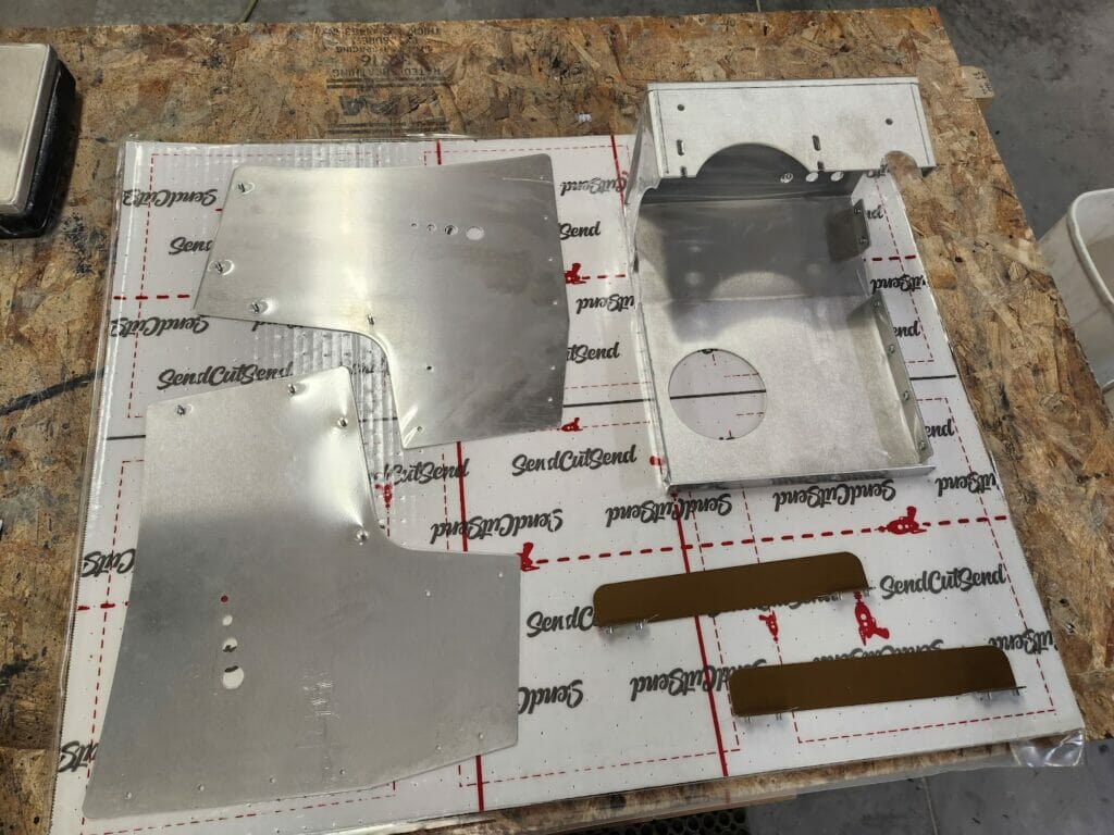
Pic. 1: The final product, securely vacuum packed for shipping.
Nuts!
Press fit nuts are a great way to securely fasten aluminum or steel panels that are too thin to tap, or in applications where using a rivet would prevent access to internal components.
In this example, we have the top panel of an appliance with tabs that will be used to attach side access panels. Although selecting hardware in the SendCutSend app will automatically resize the holes on your drawing appropriately, it’s important to confirm within your design that there is enough room for bend tolerances, and that the hardware doesn’t come too close to an edge.
Reviewing the Hardware Catalog, shows that for a 10-32 nut, we’ll need 0.252” diameter holes.
When adding the press-fit nut to confirm our clearances we have two options: download the fastener from the PEM Catalog, or use the SolidWorks Toolbox. Let’s start with the integrated solution and use the catalog later, in the next example.
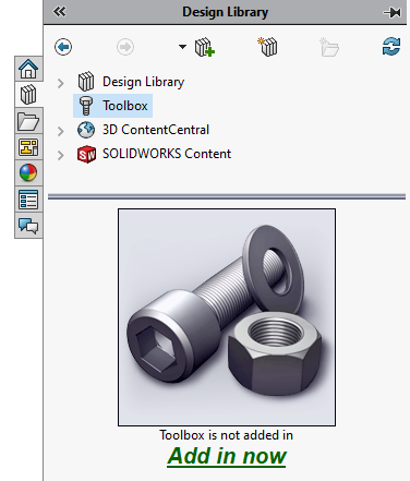
To insert PEM hardware from within SolidWorks, access the Toolbox Wizard by opening up the right menu and selecting “Add in now”.
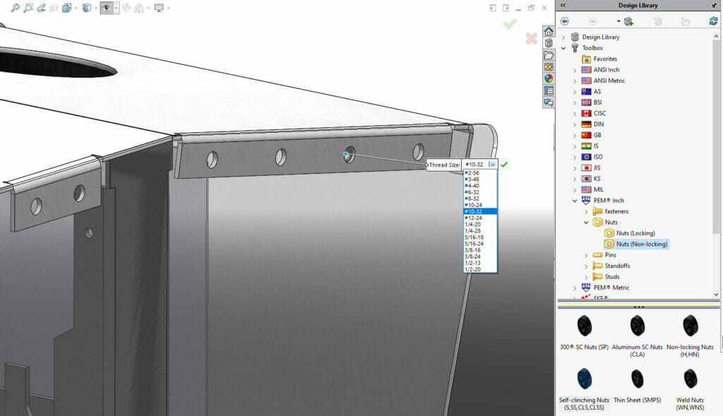
Once enabled, expand the list of fasteners. Note that there are both Metric and Inch unit PEM fasteners to choose from. To add the fastener to your assembly, drag-and-drop it onto one of the holes in the assembly and the fastener will snap into place.
When we’re confident that the fastener size and placement are just right, we simply save the sheet metal part to DXF, fire up SendCutSend, and drop the file in to get started. In this case we’ll use 2mm thick 5052 aluminum because it’s lightweight, corrosion resistant and inexpensive. After selecting the alloy and thickness we can quickly add bending and hole operations.
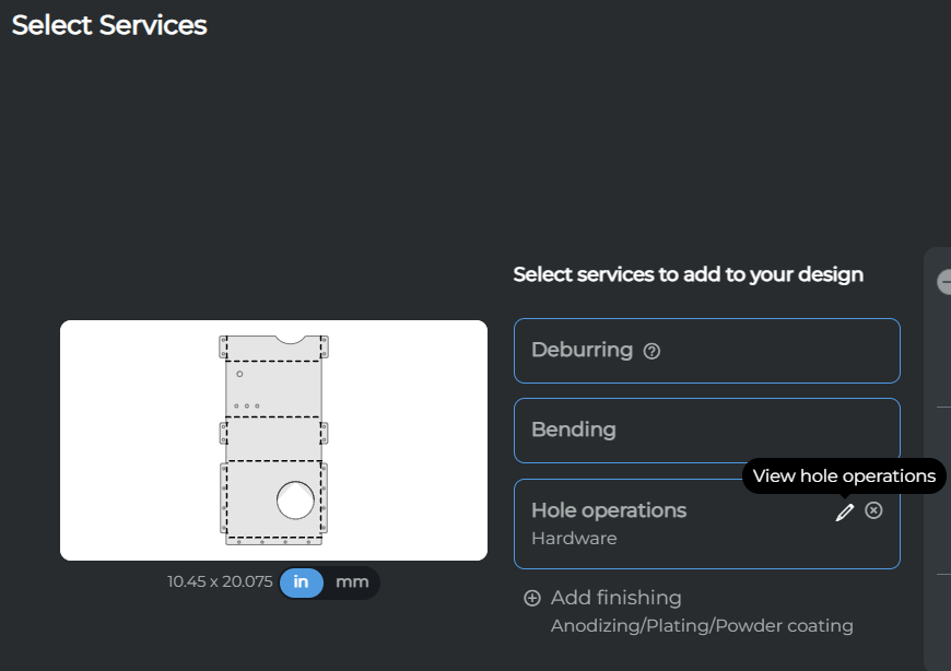
Opening up the Hole Operations menu shows that the app has detected all the holes and helpfully categorized them by diameter. Since we want all our ¼” holes to get the same 10-32 nuts, we can group-select that hardware, and the face on which it should mount.
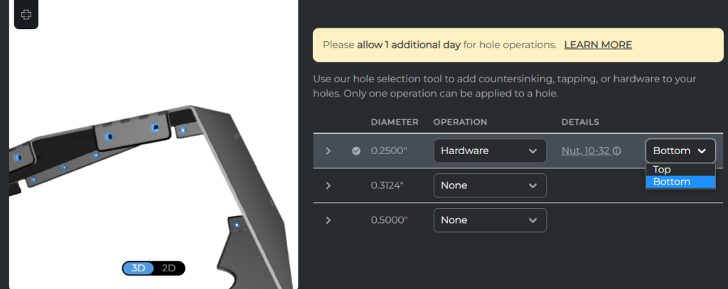
The 3D view within the preview window makes it super easy to both confirm bend direction and hardware placement, so we can be sure the part arrives just the way we drew it in CAD. This small amount of extra time will save you lots of potential headaches down the road. Now let’s take a look at adding studs to the side panels of this same appliance.
You might be curious just how accurate SendCutSend bending is. Below is our part, as received with no “adjustments” to the bend angles:
Send-Cut-Stud
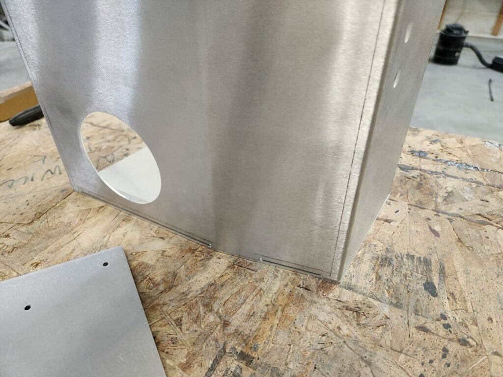
Since fasteners in the side panels will be easily visible, it’s important to think about what kind of hardware we want to stare at long-term. Since we want an uncluttered aesthetic, studs offer a great solution because they mount flush to the backside (in our case, the visible side) of the panel and with a little finishing can be made nearly invisible.
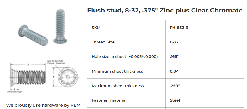
To mount the side panels to the frame, we’ll choose some ⅜” long 8-32 studs from the Hardware Catalog and note the PEM SKU.
Using this handy reference, we can search the PEM Catalog for the solid model of our exact sheet metal hardware and import it into our CAD program.
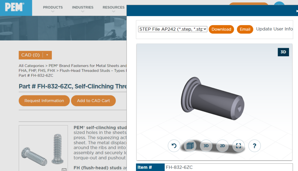
Once imported (the STEP file type often imports best), it’s easy to validate stud diameter, length and placement in relation to the panel and mounting frame.
Saving our sheet metal part to DXF and uploading to SendCutSend, we will again select material from the list of applicable materials on the Hardware Guidelines then proceed to the Hardware dialog.
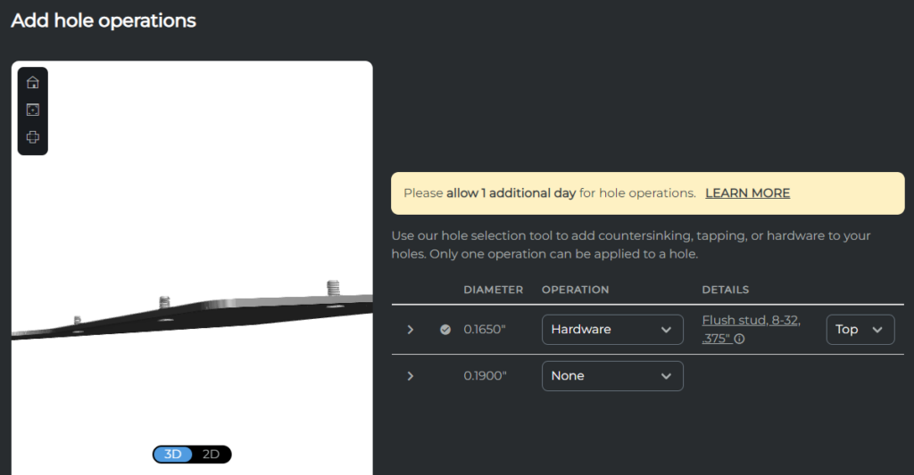
Referencing the Hardware cutsheet in figure 6 we can see that all the 0.165” holes are dimensioned to receive 8-32 studs. We can confirm the mounting face in the 3D preview. In this case, we have two identical sheet metal parts–one for either side of our assembly–but the hardware needs to be mirrored, so we must order the part twice. Remember to select the opposite face for hardware on the mirrored part!
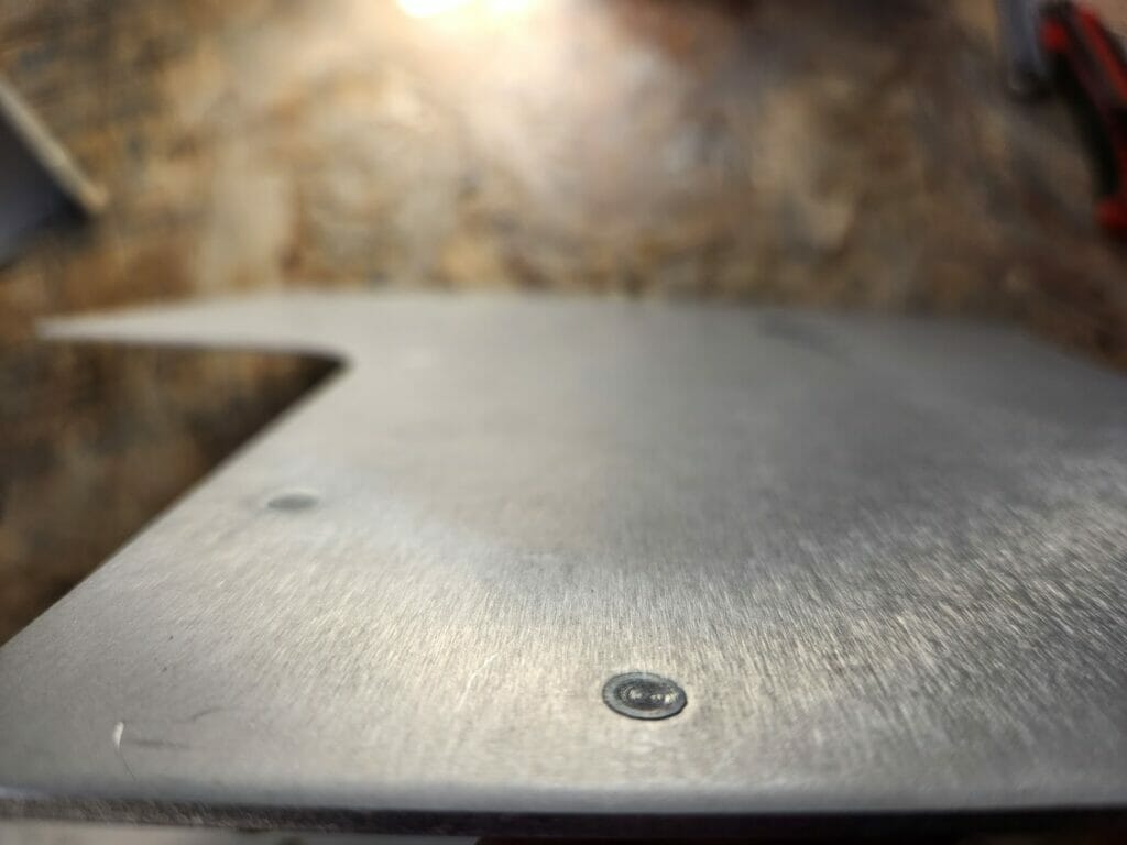
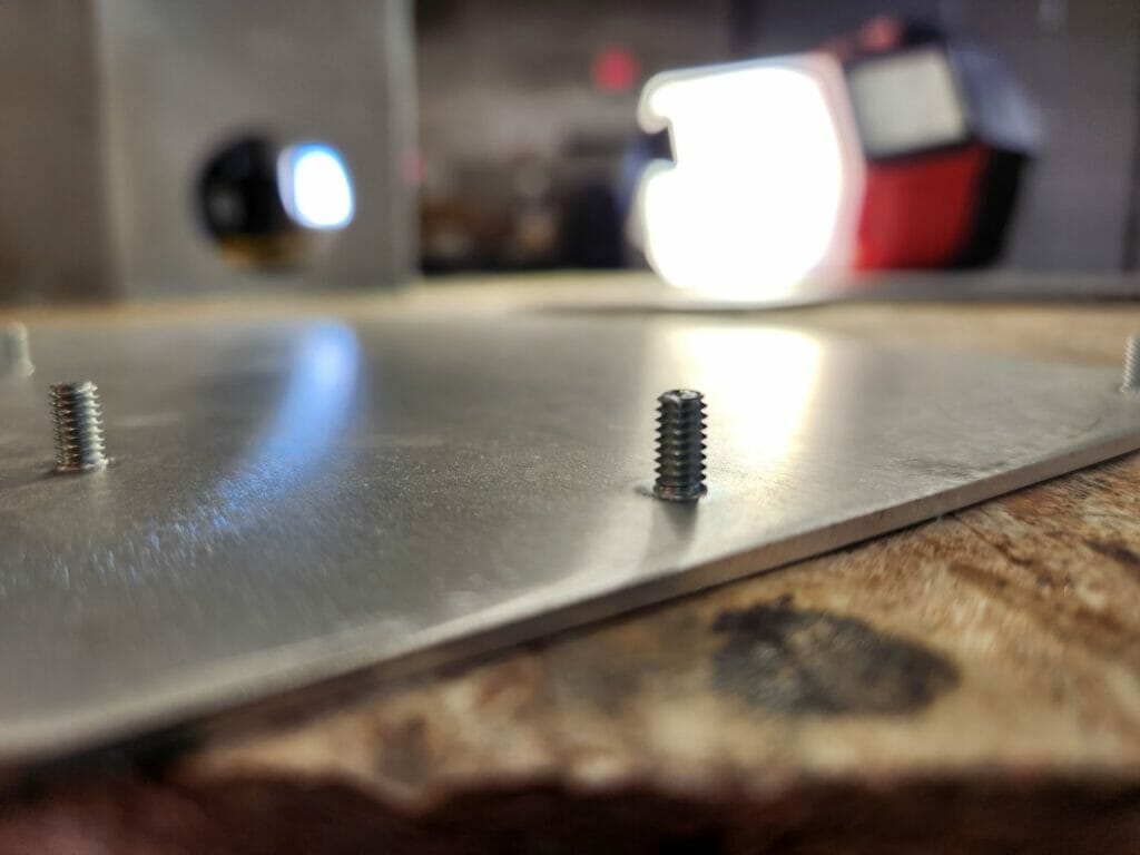
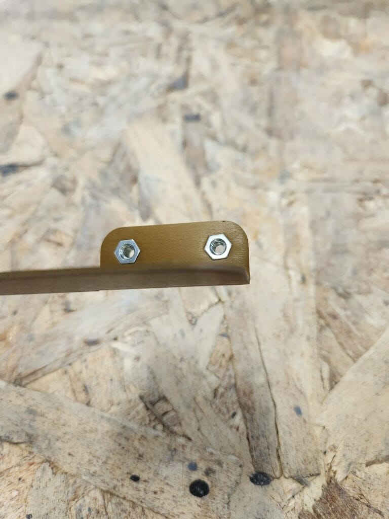
Just how do these standoffs look once installed? Below we have both the front and back faces:
Standoff-ish
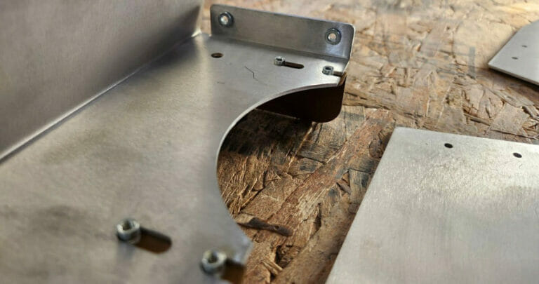
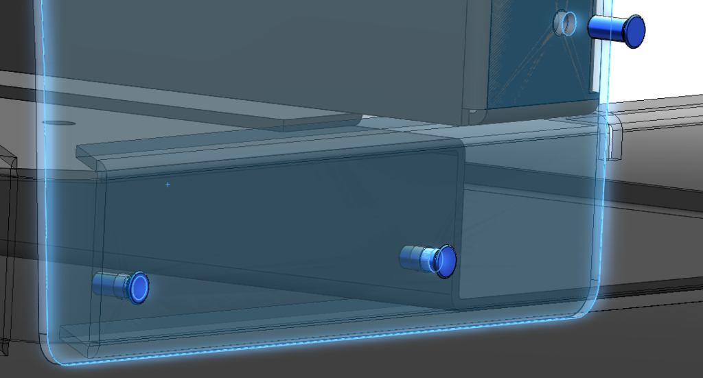
The last sheet metal hardware offering to demonstrate is the humble standoff. Aside from obvious use cases, such as PCB mounting, standoffs can also be super useful in more novel applications: Today let’s use small standoffs, along with some laser cut slots, to allow for flexible positioning of our last part example within the assembly.
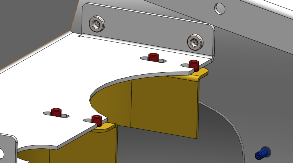
The figure shows the standoffs (red) inserted in the gold-colored shroud, allowing it to move side-to-side as needed within the slots to properly fit other components. Also pictured are a stud (blue) to mount the side panel to the frame, and a couple press-fit nuts for panel-to-panel fastening.
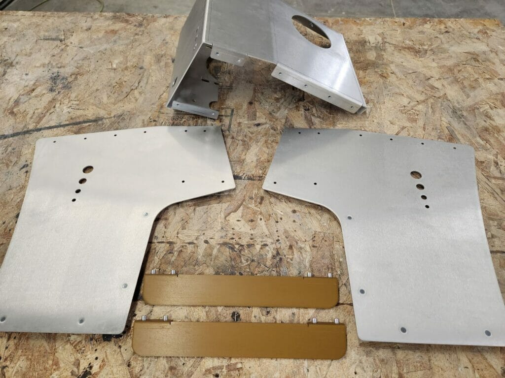
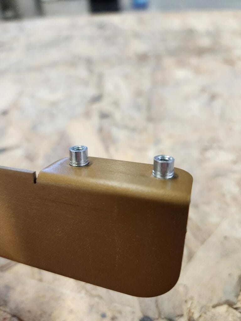
While it’s cool to see in CAD with colors, it’s way cooler in real life:
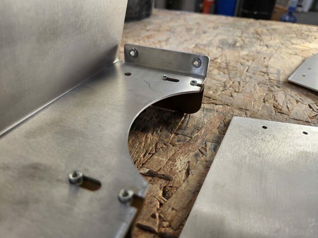
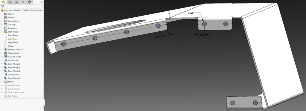
As with all hardware, it’s important when locating standoffs that you confirm the minimum distances to other features.
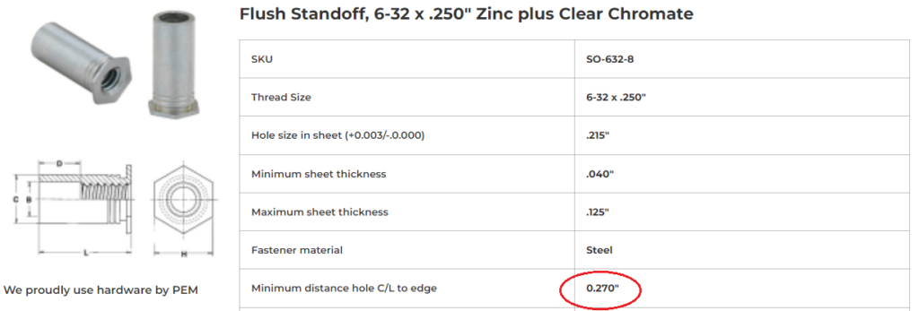
In this case, looking at the Hardware Catalog shows us that for a 6-32 standoff, we need a minimum of 0.27” from the centerline of the fastener to the edge (or bend line).
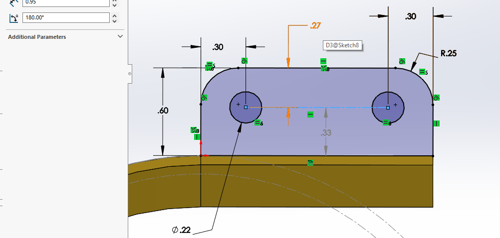
Drawing everything to scale ensures that when we upload, the app won’t turn around and say something is wrong with our design.
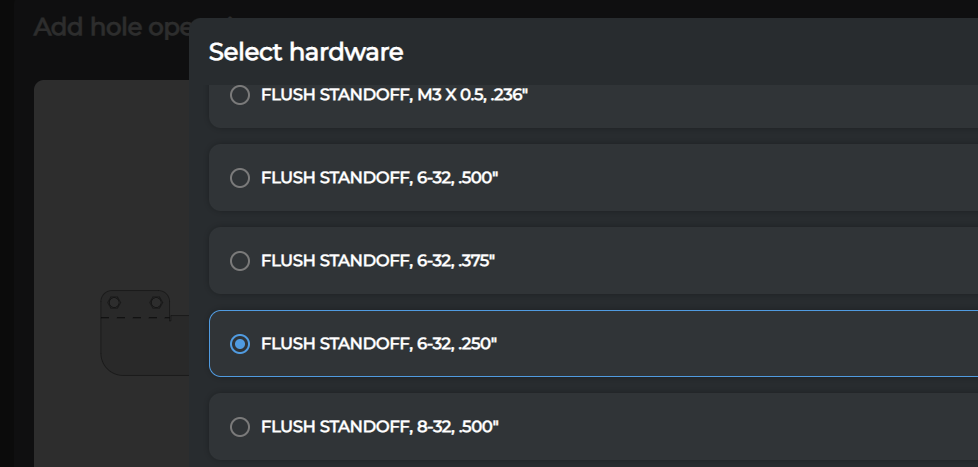
The last order of business is to export this last part as a DXF and, you guessed it; upload, bend, add hardware, and confirm in the preview window.
With this little part, we went ahead and gold anodized it as well, to show off the results of hardware and finishing services:
Fasten-ating!
There are lots of reasons to use Hardware:
- Less work for yourself on the final assembly
- To simplify an upgrade kid you want to market
- Reduce overall complexity/part count
- Not worry about corrosion, warping, thermal stress
- So many more.
Hopefully this tutorial has given you a taste of the flexibility and usability of our Hardware Insertion service. We look forward to seeing what ingenious design you come up with!


