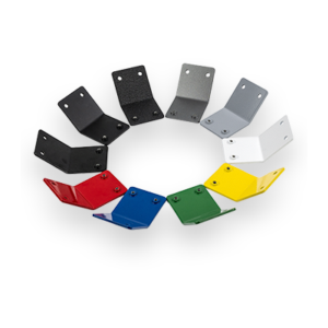
4 Thicknesses
Production Time

Laser cut, +/- .005" tolerance
Thicknesses greater than .125″ will have a factory #1 mill finish. When not deburred, the appearance will be dull with visible mill scaling.
With high amounts of nickel and chromium and a lower carbon count than other stainless varieties, 316 is highly corrosion resistant. Able to remain corrosion resistant across many different environments makes this steel an important material in modern industries.
Our 316 stainless steel is very similar to 304 in application, but this material differs in one major area: corrosion resistance. By alloying molybdenum into its composition, 316 circumvents 304’s common pitfalls when it comes to rusting. Specifically, 316 is adept at resisting corrosion caused by chloride exposure. This means that it’s great for holding tanks that could come into contact with corrosive liquids, such as sea water, or chlorine.
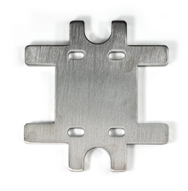
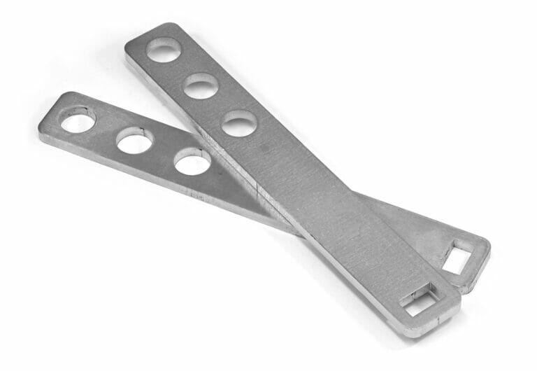
SendCutSend’s laser cut 316 stainless steel will live up to your highest expectations regarding strength and corrosion resistance. While it’s not as easy to machine as 304 stainless steel, it makes up for that in the durability it will bring to your next project. And machining is our wheelhouse, so you just sit back while we laser cut all your 316 stainless steel parts.
We guarantee awesome quality parts. If you’re not 100% happy, we’ll give you a refund or remake on the spot – no questions, no hassle.
SendCutSend offers 316 Stainless Steel in four thickness options: .060″(1.52), .125″(3.18mm), .187″(4.75mm), and .250(6.35mm).
With SendCutSend’s 316 Stainless Steel offering, you can get parts instantly quoted if they fall between .25″ x .375″ and 30″ x 34″. For larger parts, custom quotes are available for sizes up to 30″ x 56″.
You can add the following services to your 316 Stainless Steel parts:
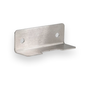
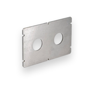
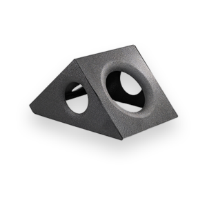
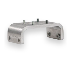
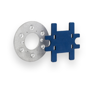
Bending, Deburring, Dimple Forming, Hardware Insertion, Powder Coating, Tapping, and Tumbling
We accept .ai, .dxf, .dwg, .eps, .stp, and .step
Customize one of our simple parts templates

316 stainless steel is part of the 300-series austenitic alloys, known for toughness, ductility, and corrosion resistance. The addition of 2–3% molybdenum is what separates 316 from 304 stainless, giving it superior performance in chloride-rich environments like saltwater, pool chemicals, or industrial processing plants. At SendCutSend, 316 stainless is offered in multiple thicknesses and cut on industrial fiber lasers for precision, clean edges, and fast turnaround.
316 is essentially the upgrade to 304 when corrosion is a concern. Both grades are strong, weldable, and bendable, but 316 shines in marine and chemical environments where 304 will pit or tea stain.
If you’re building indoor brackets or cosmetic enclosures, 304 is often enough. If your project faces saltwater or chemicals, 316 is the clear choice.
Yes. 316 stainless is an excellent candidate for fiber laser cutting, the method used at SendCutSend. Fiber lasers cut reflective metals cleanly, holding tolerances of ±0.005″. We use nitrogen assist gas to create oxide-free edges that are bright and ready for finishing. Oxygen cutting is faster but leaves discoloration, which is less suitable for cosmetic parts.
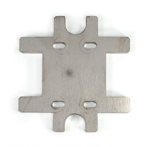
316 cuts with crisp, narrow kerfs on a fiber laser. Heat tint may appear on edges if oxygen is used, but with nitrogen, edges are bright and clean. Burrs or dross are minimal on thin to mid-thickness sheets, though very thick plate can show some edge buildup. Warping is possible in thinner sheets if designs have dense cutouts, but SendCutSend’s process minimizes heat distortion compared to plasma or waterjet.
At SendCutSend we guarantee ±0.005″ cutting tolerance on 316 stainless.
For exact data by thickness, see our 316 stainless specifications.
You can choose to have your 316 stainless steel parts deburred or tumbled for a small additional fee. In addition, SendCutSend offers powder coating on 316 stainless which adds a durable, chip-resistant layer in multiple color options, enhancing corrosion resistance for outdoor or marine projects. Explore all finishing service options at SendCutSend
316 stainless bends cleanly on a CNC press brake, though it requires careful design.
Welding is straightforward, especially with TIG or MIG. 316L is best for welded parts, as the reduced carbon minimizes carbide precipitation. Post-weld passivation restores corrosion resistance. See our bending guidelines for exact dimensions needed for bending services through SendCutSend.
SendCutSend offers several services to make your 316 parts assembly-ready right out of the box:
Combining these with cutting and finishing creates a true one-stop workflow.
316 can be DIY-cut, but it’s difficult without industrial equipment. Plasma cutting leaves heavy dross, CO₂ lasers struggle with reflection, and tooling wear is high when machining. Outsourcing to SendCutSend gives you ±0.005″ tolerance, oxide-free edges, finishing, and add-on services — all with parts shipping in 2–4 days. For most engineers and makers, outsourcing is faster, cheaper, and more reliable than tackling 316 in-house.
316 stainless steel is the go-to choice when corrosion resistance matters most, especially in marine, chemical, and food-grade environments. At SendCutSend, we make it easy to turn this premium material into precision parts with our fiber laser cutting, finishing, and post-cutting services. Whether you need simple brackets, complex assemblies, or corrosion-resistant components ready for the outdoors, we deliver fast, accurate results so you can focus on your project instead of the fabrication.