7075 Aluminum is our toughest and strongest aluminum alloy. Like 6061 aluminum, 7075 aluminum was made for use in the aerospace industry, where it’s used extensively. It’s lightweight and durable, so it also lends itself to bike frames, rock climbing equipment, and other high stress environments.
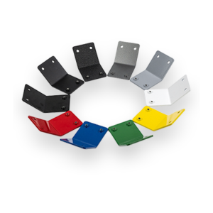
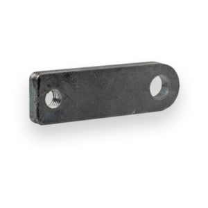
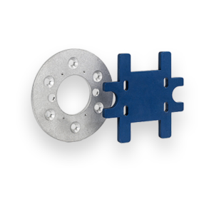
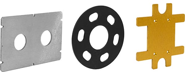
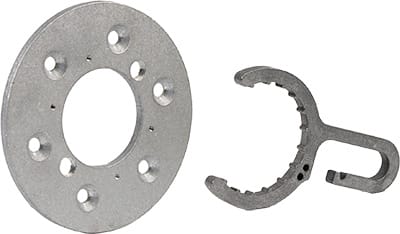
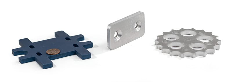
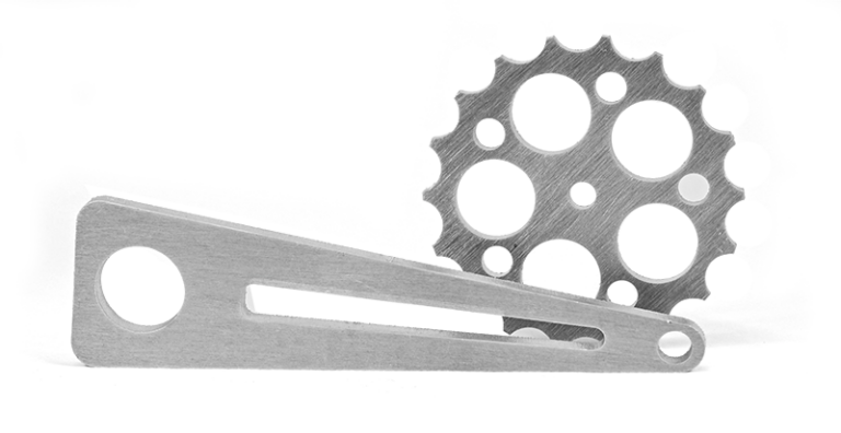
What can you make with 7075 T6 Aluminum parts?
7075 sacrifices some of 5052 aluminum’s workability, formability, and weldability for increased hardness, strength, and overall toughness.
Still carrying the benefits of other aluminum alloys, such as lower weight and high fatigue strength, 7075 aluminum positions itself dominantly as having one of the best strength to weight ratios in any aluminum alloy.
Construction angles
Automotive frames
Bicycle frames
Aerospace components
High-Stress Structural
Electronics
Heat sinks
Rock climbing equipment
And so much more!
Our laser cut aluminum sheet metal parts are guaranteed
We guarantee awesome quality parts. If you’re not 100% happy, we’ll give you a refund or remake on the spot – no questions, no hassle.
With SendCutSend’s 7075 T6 Aluminum offering, you can get parts instantly quoted if they fall between .25″ x .375″ and 30″ x 44″. Custom quotes are available for sizes up to 30″ x 56″.
You can add the following services to your 7075 T6 Aluminum parts:
Anodizing, Countersinking, Deburring, Hardware Insertion, Powder Coating, Tapping, and Tumbling
Start your first SendCutSend project today!
Upload your CAD design, or try one of our customizable part templates to get instant pricing on your custom laser cut parts. All delivered to your door in a matter of days.
7075 aluminum: Deep dive into properties, fabrication, and use cases
7075 aluminum is the strongest aluminum alloy offered by SendCutSend, known for its exceptional strength-to-weight ratio and use in aerospace, motorsports, and high-performance engineering applications. It’s part of the 7xxx series, which uses zinc as its primary alloying element to achieve tensile strengths that rival low-carbon steels — all while remaining significantly lighter. While 7075-T6 provides outstanding performance under load, it comes with trade-offs: limited corrosion resistance, low weldability, and more challenging formability. This guide covers everything you need to know before designing, cutting, and finishing parts in 7075 aluminum.
Key things to know about 7075 aluminum
High-strength alloy: 7075-T6 is one of the highest-strength aluminum alloys available, offering near-steel performance at one-third the weight.
Zinc-based composition: The addition of zinc and small amounts of magnesium and copper gives 7075 its superior strength and fatigue resistance.
Heat-treatable: The T6 temper means the material is solution heat-treated and artificially aged to reach its maximum strength.
Moderate corrosion resistance: Performs well indoors and in dry environments but is prone to corrosion in marine or high-humidity conditions.
Poor weldability: 7075 is not recommended for welded assemblies; it can crack under localized heat.
Excellent machinability: Despite its hardness, 7075 machines beautifully with the right tooling and feeds.
Laser-cut precision: SendCutSend cuts 7075 aluminum sheet to ±.005” tolerance with 2–4 day lead times before shipping.
Mechanical & physical properties of 7075-T6 aluminum
The T6 temper represents the peak-strength condition for 7075 aluminum — achieved through solution heat treatment and artificial aging. It’s one of the few aluminum grades strong enough to replace steel in many structural applications while maintaining excellent fatigue strength.
Tensile Strength (Ultimate): ~83,000 psi, one of the strongest aluminum alloys available
Elongation at Break: 11%, moderate ductility for limited forming
Hardness: Brinell ~150 HB, considerably harder than 6061 or 2024
Density: 0.101 lb/in³, slightly denser than 6061, still very lightweight
7075-T6 is one of the highest strength-to-weight aluminum alloys available. It maintains excellent fatigue resistance and rigidity, but requires more careful handling during fabrication and finishing.
Strengths & advantages of 7075 aluminum
Exceptional strength-to-weight ratio 7075-T6 rivals mild steel in strength while being about one-third the weight. This makes it ideal for structural components where both strength and weight savings are critical.
Superior fatigue resistance Excellent under repeated stress, 7075 performs exceptionally well in load-bearing, cyclic, and dynamic applications such as suspension parts, aircraft components, and performance hardware.
High machinability 7075 cuts cleanly and maintains excellent surface finishes with the right tooling. It holds tight tolerances and resists galling during machining — perfect for high-precision parts.
Dimensional stability The T6 temper keeps distortion low, even in thin sections or complex geometries.
Excellent performance in dry or controlled environments When corrosion and welds aren’t factors, 7075 provides unmatched performance for mechanical, structural, and aerospace parts.
Trade-offs & limitations of 7075 aluminum
Limited corrosion resistance 7075’s high zinc content makes it more susceptible to corrosion, especially in humid or marine environments. For outdoor applications, consider anodizing, powder coating, or switching to 6061 aluminum or 5052 aluminum.
Not weldable 7075-T6 is highly prone to hot cracking during welding. Mechanical fasteners or adhesives are the preferred joining methods.
Reduced formability The high hardness of 7075 means it can crack if bent sharply. SendCutSend does not currently offer bending on 7075 Aluminum.
Heat sensitivity 7075’s strength is tied to its temper. Excessive localized heating (from laser cutting, grinding, or finishing) can reduce its mechanical properties.
Fabrication & laser cutting considerations for Al 7075
Cutting performance
SendCutSend laser cuts 7075 aluminum to a ±.005” tolerance. The alloy’s hardness provides clean, sharp edges with minimal burrs. However, heat buildup must be controlled to prevent localized softening.
Thin sheets (.040″–.125″) cut very cleanly.
Thicker sheets (.250″–.500″) may show minor dross or edge darkening, easily removed with light sanding.
7075 reflects more laser energy than 5052 or 6061, requiring higher laser power and precise calibration.
Hole size & geometry
Design guidelines are similar to other aluminum alloys but with more conservative spacing:
Minimum hole size: equal to or greater than material thickness.
Edge clearance: at least 2× material thickness to prevent microcracks.
Avoid tight internal corners or narrow slots that concentrate stress.
Heat management
Keep thermal exposure low. Prolonged heat during post-processing (grinding, sanding, etc.) can reduce the T6 hardness.
Finishing and protection
7075 takes surface finishes well. Anodizing and powder coating both improve corrosion resistance and extend lifespan in harsh environments. For structural applications requiring maximum strength and minimal oxidation, clear anodizing is common.
Use cases & applications
Because of its exceptional strength and rigidity, 7075-T6 aluminum is used in advanced engineering and performance-driven industries:
Aerospace: wing spars, bulkheads, fittings, and structural panels
Motorsports: suspension components, performance brackets, and mounts
Defense & tactical gear: firearm receivers, mounts, and optical housings
Industrial: high-stress tooling, precision jigs, and fixtures
Robotics & automation: lightweight but rigid structural frames
Performance consumer goods: camera equipment, bicycles, climbing gear, and racing parts
If your part requires maximum stiffness and minimal weight — and corrosion protection or welding aren’t concerns — 7075 is likely the top-performing alloy for the job.
Why use 7075 aluminum?
7075-T6 aluminum represents the pinnacle of strength in the aluminum family. It combines near-steel tensile strength with exceptional fatigue resistance and a low weight that makes it indispensable in performance-critical designs. While it doesn’t offer the weldability or corrosion resistance of 6061 aluminum or 5052 aluminum, its unmatched mechanical performance makes it the go-to choice for high-load, high-precision, and aerospace-grade applications. At SendCutSend, we laser cut 7075-T6 aluminum sheets with ±.005” tolerance and 2–4 day turnaround, offering the same precision and consistency as our other aluminum materials. When your design demands maximum strength and minimum weight, 7075 aluminum delivers the performance edge.