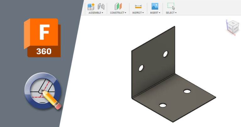
Welcome to the second installment of our three-part series on how to design your own custom laser cut parts. In this guide, we’ll take the flat metal strap part created in the first post and give it new functionality. Make sure you have Autodesk Fusion and/or QCAD installed to get the most out of this tutorial!
Autodesk Fusion has both paid and free, personal use licenses. If you’re just getting started, the personal use option is a great way to learn 3D design. We especially recommend Fusion if you need sheet metal bending services. Once Fusion is set up properly, the sheet metal tools will automatically calculate the dimensions needed in your flat part to get the final dimensions desired for your bent part.
QCAD is a straightforward program for 2D design that allows users to edit and save DXF files natively. After installing the Professional Trial version for your operating system, check out Getting Set Up with QCAD for how to remove the Professional Trial add-on so you can use the free Community Edition without interruption.
Other guides in this series:
Forget the Hardware Store – Design Custom Laser Cut Parts Instead
Forget Etsy – Design Custom Laser Cut Gifts Instead
Designing a Brace
Flat parts are all well and good, but some projects require more dimension. That’s when it’s time to get bendy.
Let’s say the strap we designed is pretty close to what we need – it just needs a bend in the middle to become a brace. Easy enough! Before we jump in, though, let’s quickly touch on bending basics.
Flat vs. Formed Dimensions
When you bend a piece of sheet metal, it stretches a little as the material is forced into a new shape. Therefore, if you want a flange’s overall length to be 5mm after it is bent, the flange’s flat, pre-bend length must be slightly shorter. How much shorter depends on the specific material and thickness.
We have in-depth guides about calculating bend allowance and deduction and technical bending terminology that anyone new to bending should read. For now though, you can simply refer to our Sheet Metal Bending Calculator. The bending calculator allows you to select the material and units, input the desired finished dimensions and bend angles you want, and see the flat dimensions you should use to design your flat pattern.
Bending Design Guidelines
Parts that will receive bending services must abide by our bending design guidelines. To find the bending specifications for your material of choice, navigate to SendCutSend’s Materials Library and locate the material.
Since we are simply revising the strap we created in the first guide, we need to refer to 0.059” G90 galvanized steel again.
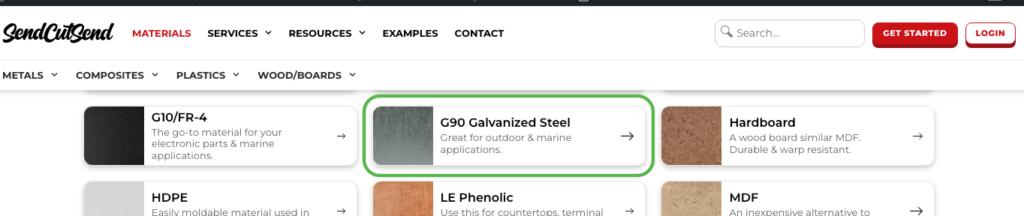
Then click to visit the material page, and scroll down to find the Material Details.
Select the thickness you need. Click to “View Specs” on the Bending tile.

For bending, scroll down further to find those specifications.

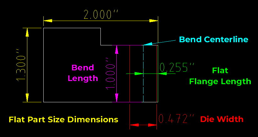
Here are brief definitions for each specification:
- Min Bend Part Size: minimum overall flat part size for bending
- Max Bending Flat Part Size: maximum overall flat part size for bending
- Max Bend Length: maximum length of actual bend/bend centerline
- Min Flange Length (Before Bend/Flat Pattern): minimum flat flange length
- Min Flange Length (After Bend): minimum formed/bent flange length
- This is how long the flange will be after bending if a flange is the minimum flat flange length in the flat pattern
- Die Width: width of bottom die that will be used to bend the material
- See Our Process: Air Bending and Die Line Considerations for more on this
- Effective Bend Radius: interior radius of flange after bending
- Max Bend Angle: maximum angle we will bend the material
- In thinner materials, we can bend as far as 130 degrees
- For thicker materials, this will be limited up to 90 degrees depending on the material
- See FAQ: How should I enter bend definitions? for further guidance on this
For the strap design,
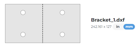
- we can see the overall flat part size (245mm x 127mm / 9.65” x 5”) is well within the allowed range for bending in 0.059” / 1.5mm G90 steel
- the bend length will end up being 127mm / 5” which will not exceed the maximum bend length for the material
- the flat flange length will be approximately half the part length for this design, so the minimum flat flange length is easily met
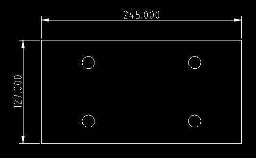
It looks like we can proceed!
For more information, we have an article covering essential bending considerations here: Design Considerations When Planning Sheet Metal Bends
Fusion Process (3D)
When planning a bent part in Fusion, the first thing to do is add a sheet metal rule for the material if you have not done this already.
What are sheet metal rules?
In 3D programs, sheet metal rules will include the information needed for the program to automatically calculate the correct formed versus flat dimensions for a part. Programs will have default rules and they may not match the properties for the actual material you will be using.
To create a sheet metal rule, navigate to the Sheet Metal tab, click MODIFY, and then click Sheet Metal Rules.
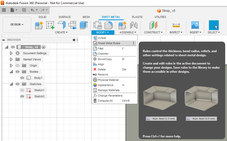
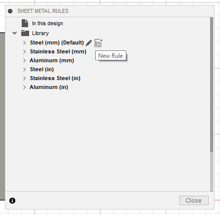
This will open the Sheet Metal Rules window. Hover over any existing rule to reveal the New Rule icon. Please note: it’s easiest to hover over a rule that already uses the units (inches or mm) that you intend to set up the new rule with.
Click the New Rule icon.
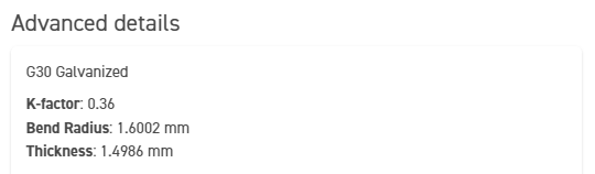
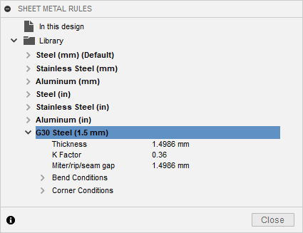
Name the rule and update the material Thickness, K Factor, and Bend radius information to match the Advanced Details located on the Bending Calculator page.
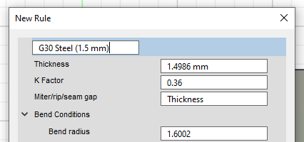
Then click Save. The rule will be added to your Library!
Once the rule has been added, we can proceed to create the part.
1. Revise Flat Design
Since we are simply revising a flat part to add a bend, that’s our first step.
The most common methods for adding bends to parts are the Bend and Flange tools. We have a detailed comparison between the tools here.
In this tutorial, we’ll use the Flange tool.
If you are designing a bent part from scratch and plan on using the Flange tool to create bends, first draw the base of your part without any flanges in the Sketch workspace.
We’ll need to update the strap part to remove the material that will become the flange.

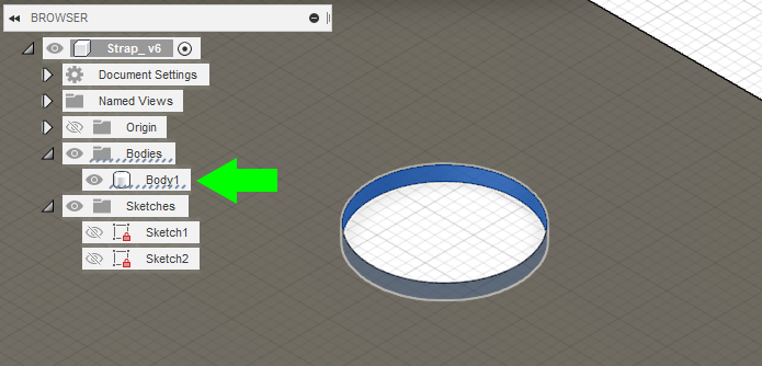
To remove two holes from one side of the part, delete them from the Body. Making the Sketch invisible by clicking the eyeball icon can make this easier. Select the features and press Delete.
Then, you can return to the top view if desired.
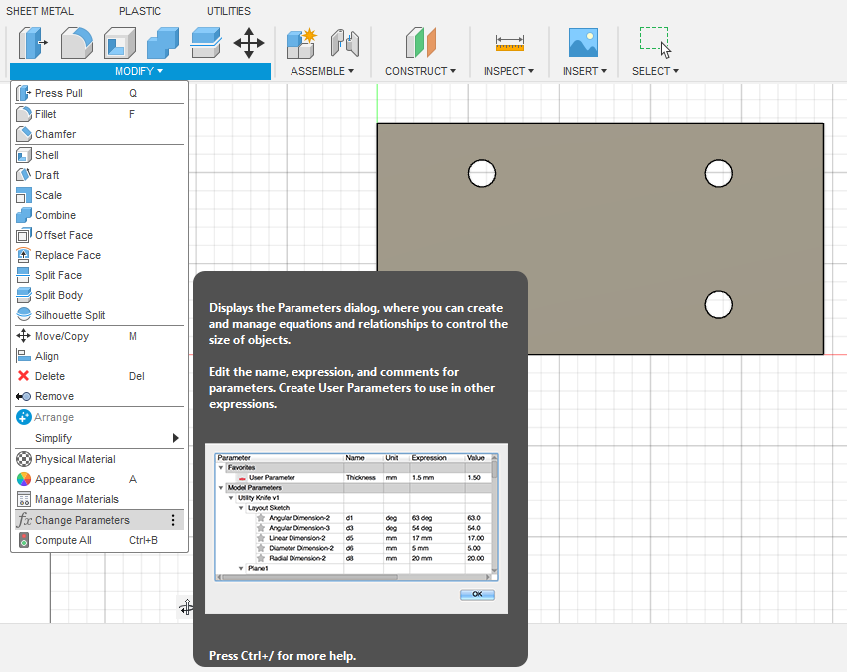
At this point, the Parameters window becomes very helpful. Access the Parameters window by clicking MODIFY to expand the dropdown menu and selecting Change Parameters.
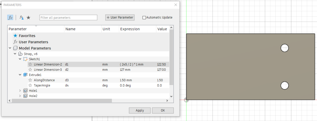
Here, we can enter the linear dimension/2 into the field and the length will be automatically halved after clicking OK, or right away if you have the Automatic Update box checked.
With just the base present in the part, we can move on to bending!
2. Convert to Sheet Metal
Under the Sheet Metal tab, click CREATE to access the dropdown menu and then click Convert to Sheet Metal.
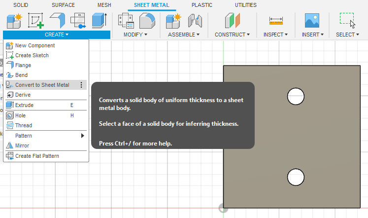
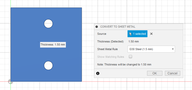
This will open the Convert to Sheet Metal Window. Select the part you want to convert to determine the Source, and then select the correct Sheet Metal Rule from the dropdown menu. Click OK.
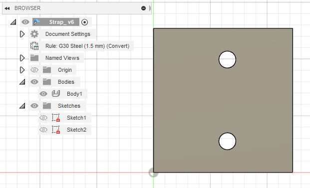
Once the part is converted, you’ll see that the sheet metal rule is being applied in the Document Settings.
Note: you can also convert a part to sheet metal using the Flange tool itself. Learn how to do this here.
3. Add Your Flange
Now for the fun stuff! Under the Sheet Metal tab, click CREATE to access the dropdown menu and then click Flange.
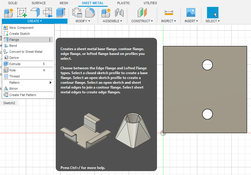
This will open the Flange window.
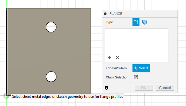
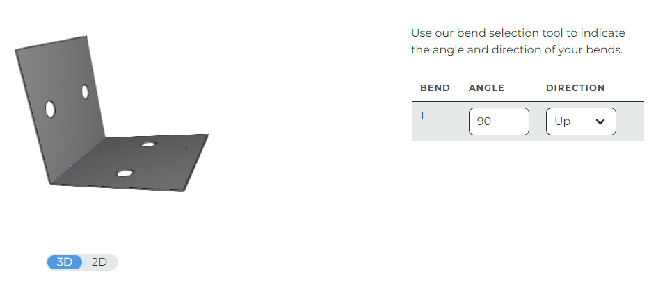
Once you select the edge you want to add the flange onto, you’ll see more options. You can also click the home view at the top right to get a better idea of what the bent part will look like.
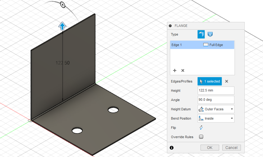
For this part, the desired flange height is 122.5mm with a 90-degree angle. Leave the Height Datum as Outer Faces and the bend position as Inside.
Once your settings are correct, click OK.
4. Add Features to Flange
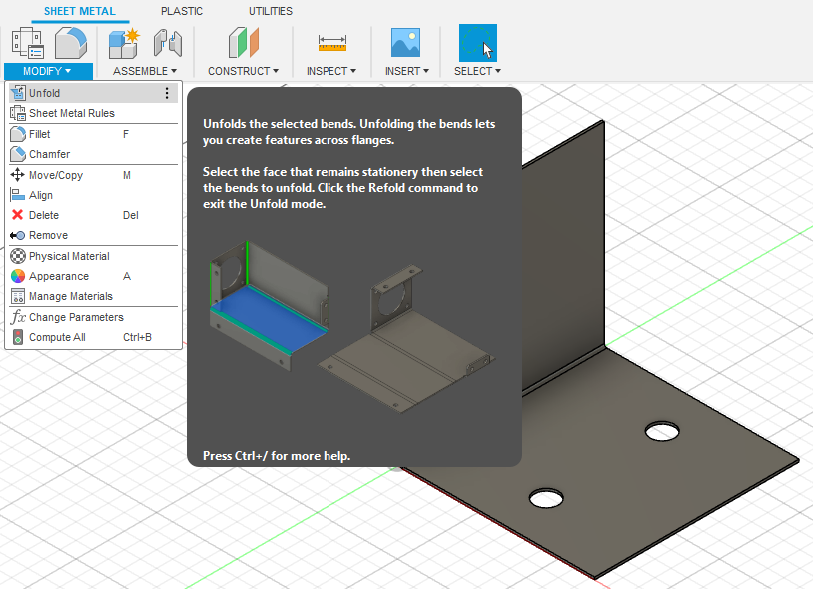
If you need holes or other features in your flange, unfold the part and make any changes needed.
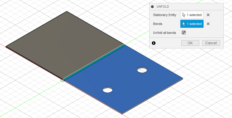
Under the Sheet Metal tab, click MODIFY, then Unfold.
This will open the Unfold window. Click either the entity you want to stay flat, or the bend you want to unbend. Check or uncheck the Unfold all bends box as needed.
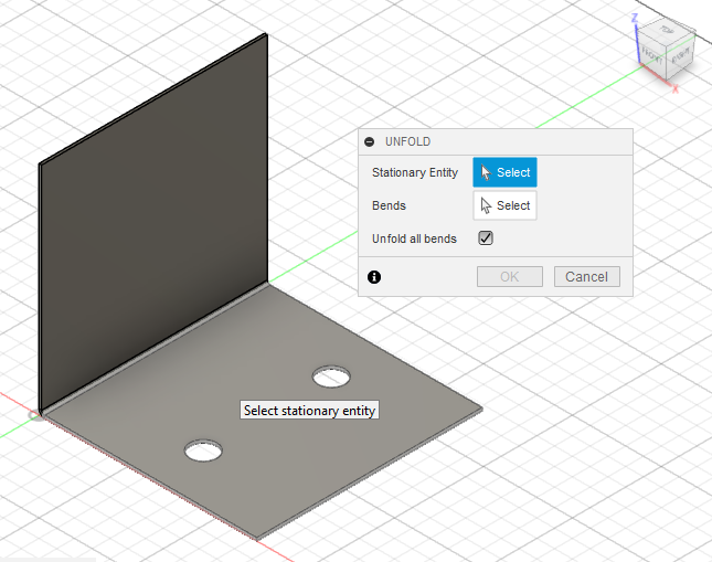
When you make sections, you’ll be able to preview the unfolded part before clicking OK.
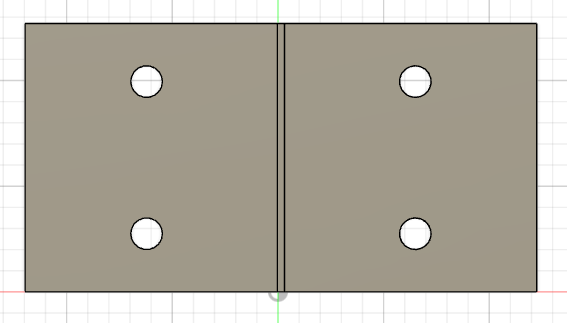
Here, we’ll redraw the holes on the other side using the Hole tool method described in the first post.
Once the part is updated as needed, we’re ready to export!
5. Export DXF Using Flat Pattern Mode
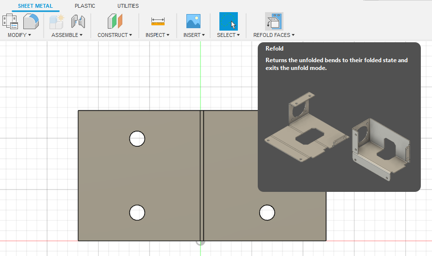
Because our part is unfolded, we’ll need to re-fold it by clicking Refold Faces before we can export the DXF.
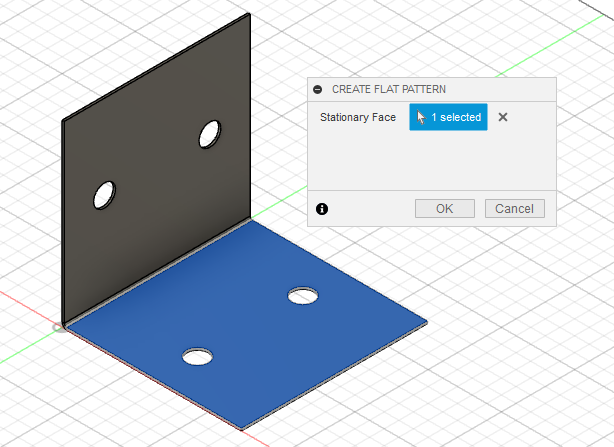
Once that is done, under the Sheet Metal tab click CREATE, then Create Flat Pattern.
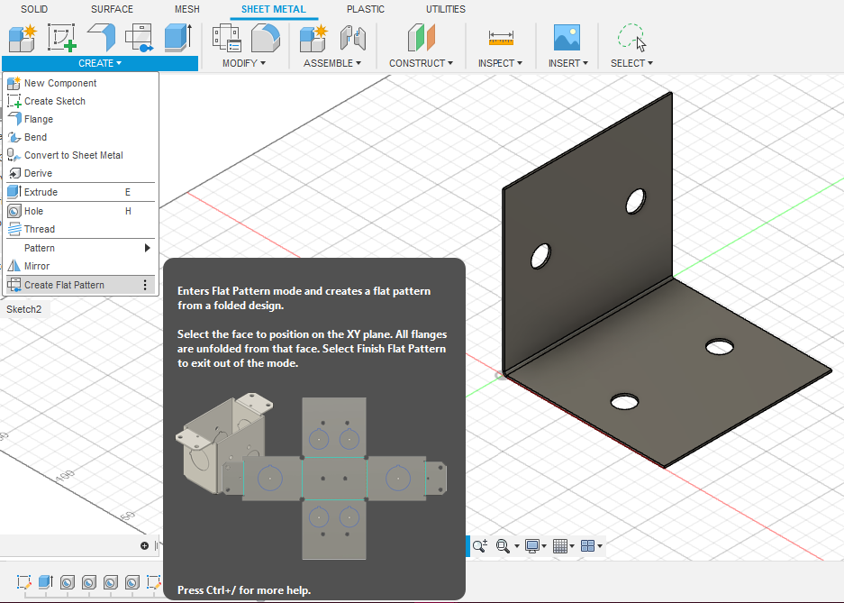
This will open the Create Flat Pattern window. Select the Stationary Face and click OK.
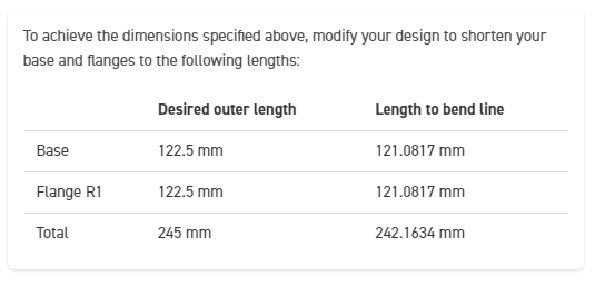
This will create the flat pattern that will actually be cut by the laser. Now is a great time to use the Measure tool to check that the flat dimensions match what the Bending Calculator advises.
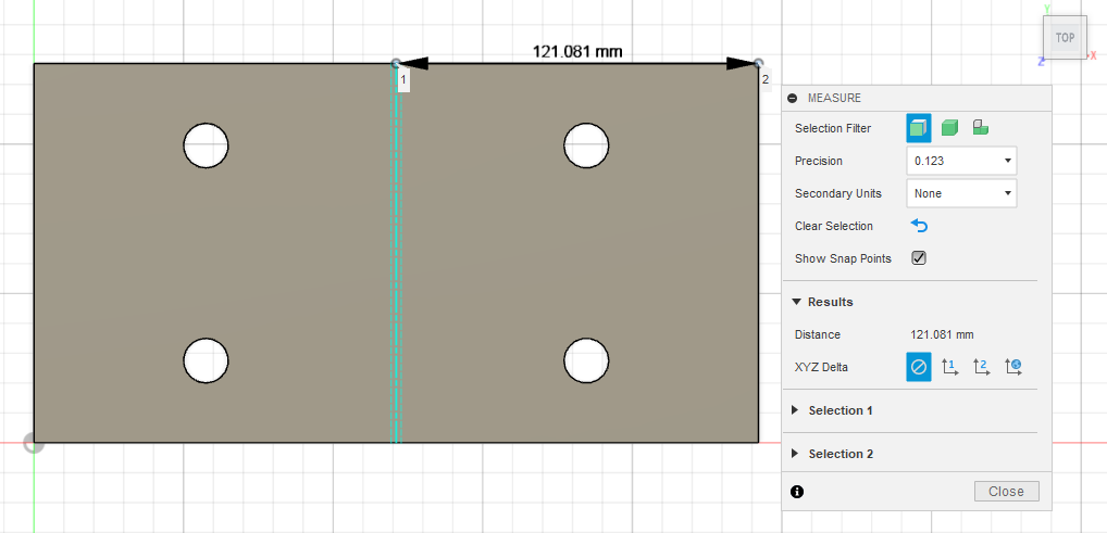
You can also check to ensure all hole-to-edge distances are correct.
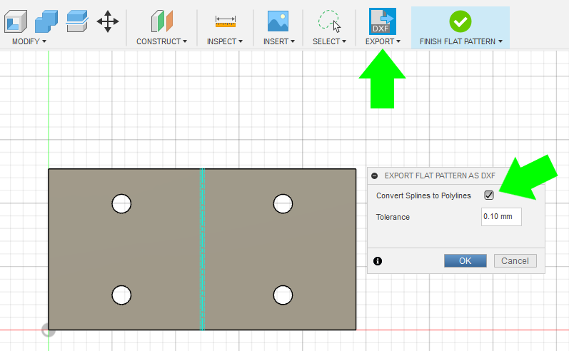
When the design is ready, click DXF Export, and then tick the Convert Splines to Polylines box in the Export window. Then Click OK.
If you run into any trouble exporting your flat pattern, check out our in-depth guide here: How To Export a DXF from Autodesk Fusion.
6. Upload to SCS Website
When the DXF is uploaded to SendCutSend’s website, the part preview should show the correct flat dimensions and a dashed bend line. This will allow you to add bending services and configure the part after you have selected a material that is eligible for bending.
QCAD Process (2D)
In QCAD, we’ll essentially follow the same process as when designing the strap except we’ll create the rectangle and add the bend line based on the Bending Calculator dimensions.

1. Revise Flat Design
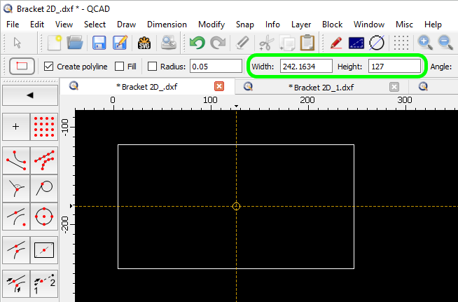
As with the strap, we’ll use the Rectangle With Size tool (keyboard shortcut RS) to draw the rectangle.
2. Add Bend Line
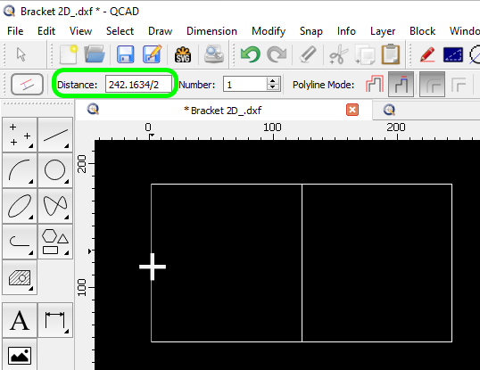
Then we’ll use the Offset (with Distance) tool (keyboard shortcut OF) to add the bend line.
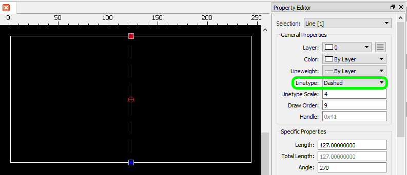
Then, set the bend location line to Linetype: Dashed.
This setting is updated in the Property Editor (keyboard shortcut GP). You can update this setting by selecting the bend location line with your cursor (keyboard shortcut QQ) and selecting the correct linetype from the dropdown menu.
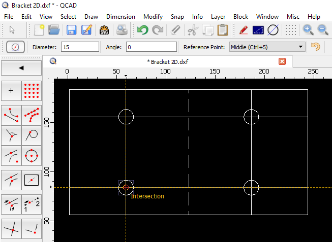
3. Add Guide Lines and Features
Once this is done, follow the same steps for adding guide lines and circles as when designing the strap. Add guide lines using the Offset tool and then create and place your circles on the guide line intersections using the Center, Diameter tool.
4. Delete Guide Lines
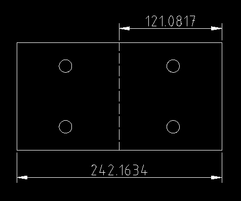
Then, delete the guide lines and double check that all dimensions are correct.
5. Save the DXF
When the design is ready, save the DXF.
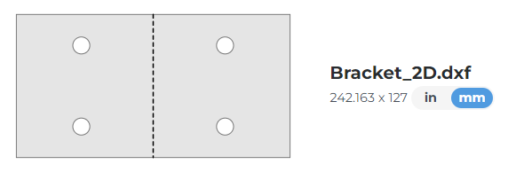
6. Upload to SCS Website
The DXF file should upload successfully to the SCS website with a bend line you can configure!
You may have noticed that there is a slight difference in total flat length between the design created in QCAD versus the one created in Fusion. Depending on the material and thickness, there may be minor variances in how a 3D program calculates the needed flat dimensions versus SendCutSend’s bending calculator. You’ll only notice this if designing in millimeters since any discrepancy will be extremely small – around 0.002mm or 0.00078” at the most. This is well within SendCutSend’s cutting and bending tolerances.
Conclusion
With a little introductory knowledge and time, anyone can create custom bent sheet metal parts thanks to free design software programs. SendCutSend is here to help you take the next step by cutting, processing, and even finishing parts affordably. Design with our guidelines in mind, then upload your files – we’ll do the rest!
For more tips on working in Autodesk Fusion or QCAD, see our Fusion and QCAD archives.
Some projects require practical solutions while others need personalization. If you want to create something decorative, check out the next guide in this series: Forget Etsy – Design Custom Laser Cut Gifts Instead
Want to know what happens after you place an order? Learn about SendCutSend’s processing times and shipping speeds.
