3 Thicknesses
Production Time

CNC routed, +/- .005" tolerance
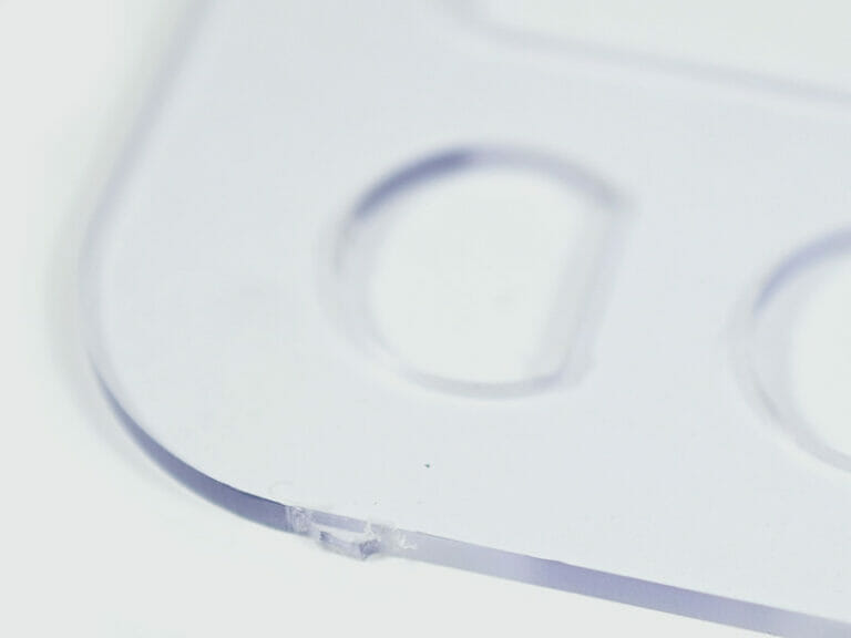
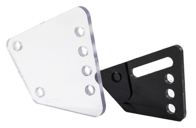
These tabs hold your parts in place while being cut to ensure the best accuracy possible. Click below to learn what to expect and how to best design with these tabs in mind.
This impressively tough and transparent material can withstand high impact over a wide range of temperatures, has a high heat deflection temperature, and has a high modulus of elasticity, making it a great fit for construction applications such as windows, skylights, and roof domes. Of course, that’s only an extremely small view into what polycarbonate is capable of in the industry.
Polycarbonate / Lexan® material absorbs very little moisture and has high-voltage insulating properties. This makes it ideal for use in electrical and electronic components. Its transparency also makes it a superior option for structural applications that require healthy sightlines.
Polycarbonate is commonly used in anti-ballistic panels (aka bulletproof glass). If that doesn’t stand testament to its impact absorption, we’re not sure what else would. If you still need more convincing, it’s also got a lot of other great stuff:
We guarantee awesome quality parts. If you’re not 100% happy, we’ll give you a refund or remake on the spot – no questions, no hassle.
SendCutSend offers Polycarbonate in three thickness options: .118″ (3.0mm), .177″ (4.5mm), and .220″ (5.6mm).
SendCutSend offers Polycarbonate with clearly defined size and thickness options. For instant quoting, the smallest part size available is 1″ x 2″, while the largest part supported is 30″ x 44″. For larger projects, custom quotes are available for sizes up to 30″ x 47″.
You can add the following services to your Polycarbonate parts:
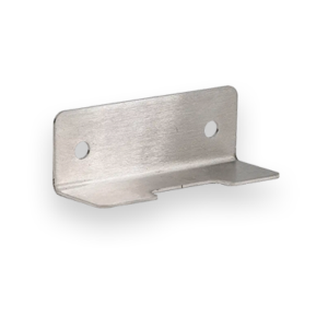
Bending and Tapping
We accept .ai, .dxf, .dwg, .eps, .stp, and .step
Customize one of our simple parts templates

Polycarbonate is an amorphous thermoplastic prized for its unique combination of toughness, optical clarity, and heat resistance. It is commonly used for safety glazing, machine guards, medical equipment, and protective enclosures. Unlike acrylic, which is stiffer but more brittle, polycarbonate can absorb impact without shattering. At SendCutSend, we machine polycarbonate sheets on CNC routers for precise, chip-free cuts, and now also offer bending and tapping services to expand how this versatile material can be used.
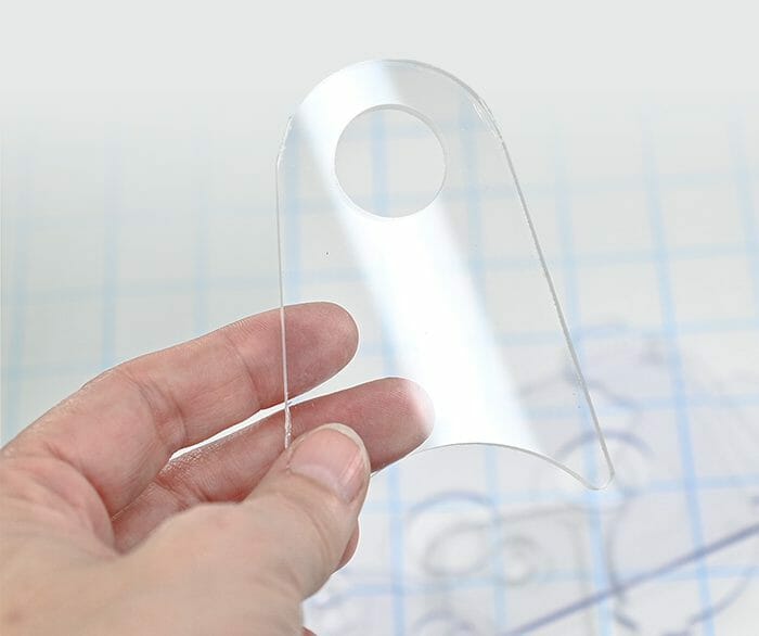
Polycarbonate combines light weight and toughness in a way that few plastics can match. It’s about half the weight of glass while offering up to 250x more impact resistance.
These properties make polycarbonate an ideal choice for protective covers, shields, and enclosures where both visibility and durability matter.
Polycarbonate does not respond well to laser cutting. The material tends to burn, discolor, or emit unpleasant fumes under a CO₂ laser. Instead, CNC routing is the preferred method. At SendCutSend, we cut polycarbonate exclusively on CNC routers, which deliver:
CNC routing produces crisp, accurate edges, but there are still a few considerations:
In short, CNC routing is the cleanest, safest, and most precise method for cutting polycarbonate sheets.
At SendCutSend, polycarbonate parts are cut to ±0.005″–0.010″, depending on thickness.
For critical features like tapped holes or tight-fit assemblies, it’s best to consult our design guidelines before uploading your file.
Yes. Polycarbonate can be bent using two common methods:
Compared to acrylic, polycarbonate bends far more reliably without cracking, making it a better choice for protective covers or enclosures.
To ensure successful bends, keep in mind:
For exact numbers and flange length requirements, see our bending guidelines.
Yes, polycarbonate is more prone to scratching than glass. Over time, it can also yellow with prolonged UV exposure.
For indoor machine guards, clarity lasts a long time. For outdoor or architectural uses, UV-protected grades are worth considering.
Polycarbonate is widely used where toughness, clarity, and formability matter:
DIY cutting of polycarbonate is possible with the right blades and routers, but it’s tricky:
Outsourcing to SendCutSend ensures:
For prototypes or precision parts, outsourcing is usually faster and produces higher-quality results.
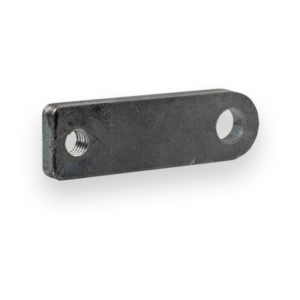
Yes. Polycarbonate can be tapped to create threaded holes for fasteners, though design considerations apply:
This service saves time by delivering polycarbonate parts ready to assemble out of the box.
Polycarbonate is a tough, clear thermoplastic that bridges the gap between strength and optical clarity. While it doesn’t laser cut well, SendCutSend machines it on CNC routers for smooth edges and tight tolerances, with optional bending and tapping services to expand its use in protective covers, enclosures, and assemblies. Whether you need flat guards, bent housings, or threaded panels, SendCutSend delivers production-ready polycarbonate parts in just a few days.