Designers make decisions that have downstream consequences in their workflow all the time. One of the first decisions when designing a new product is when to use sheet metal instead of structural shapes. Some of the benefits of sheet metal design include flexibility, decreasing overall weight, and creating shapes that are not possible with structural angles and channels. The decision of what material to use, what thickness, and what finish the parts will have are all considerations based on the product and how it will be used.
What to Consider When Designing Tabs and Slots With Sheet Metal
Does your design need reinforcements?
When designing with sheet metal, designers might need to add reinforcements with gussets and cross members. Occasionally parts must fit together without welding, and the alignment of parts must be held to a tight tolerance. Often, a jig must be designed and built to fabricate the product and hold parts in place during welding. Many of these situations can be avoided with tabs and slots in your laser-cut parts
Designing with tabs and slots also allows for a higher degree of flexibility in your product design. Additionally, there is a time and cost-saving benefit if a welding jig does not need to be created to align the parts together. Designers can also vary tab and slot size so that only a specific part can fit in a particular location.This is often called Poka Yoke, or mistake-proofing a design.
When designing with tabs for SendCutSend we recommend the following:
Slot width
Tab width + the tab material’s cut tolerance x 2
Slot height
Tab material’s thickness + tab material’s positive thickness tolerance + slot materia’s cut tolerance x 2.
The width and length of your slot should be dictated by how precise the placement of the joining part needs to be, and whether the parts will be powder coated before assembly. If a powder coat is added to the parts before they are assembled, the slot size will be smaller. Powder coating adds .002″-.005″, per surface, to a part. So, if your tab is 1″ wide, it should be 1.004″-1.010″ in width if you plan to powder coat. The same considerations should be taken for the height of the slot.
How will your final product be assembled?
Another consideration in design is how the final product will be assembled. A shelf or gusset can’t be placed into another part or assembly without enough clearance for the tabs. The pictures below show some samples of how tabs and slots can be used.
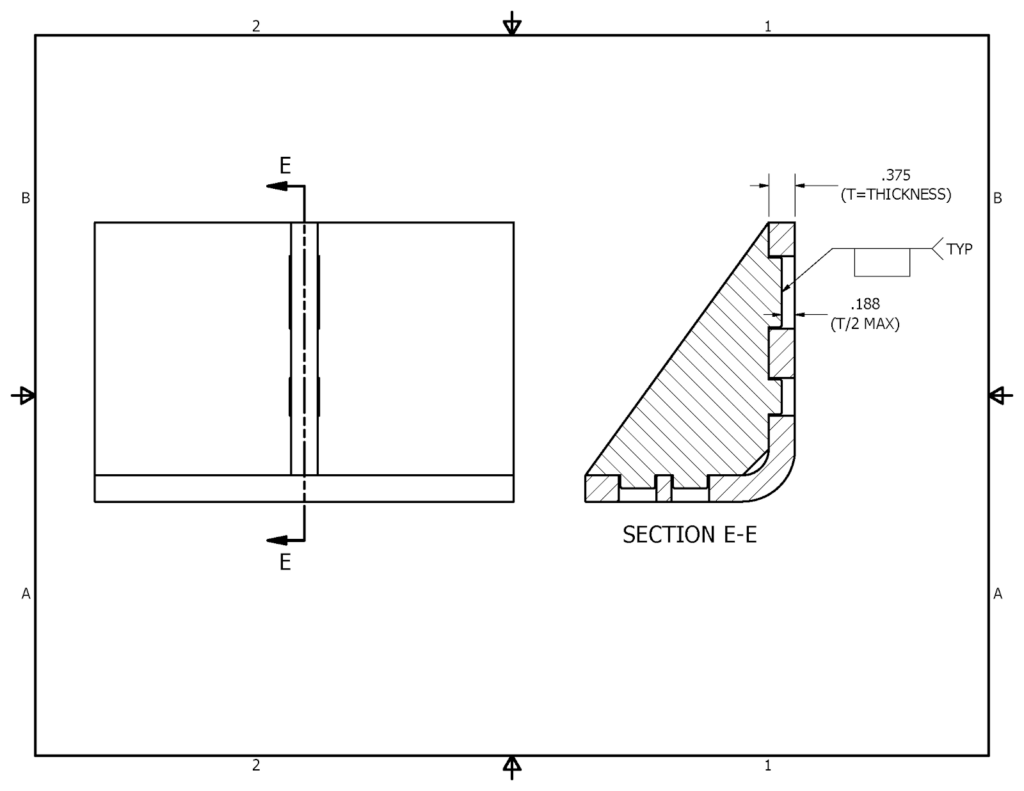
A slight chamfer or fillet on the outside corners of the tab can help the tab fit up to the slot easier. The tab length is important to consider, based on how the parts are to be used. If the tab sticks out past the mating part, it might be too long. If it is too short, it might slip out of the slot or can’t be plug welded easily. Plug welding the tab into the slot allows for fast assembly and ease of welding. The following welding detail shows how that can be achieved. Generally, the tab should be .5 to .75 the depth of the mating part.
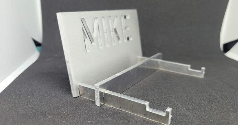
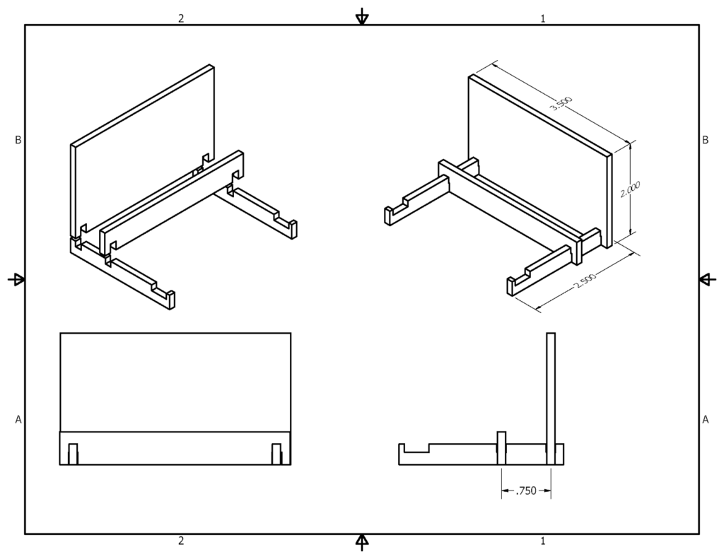
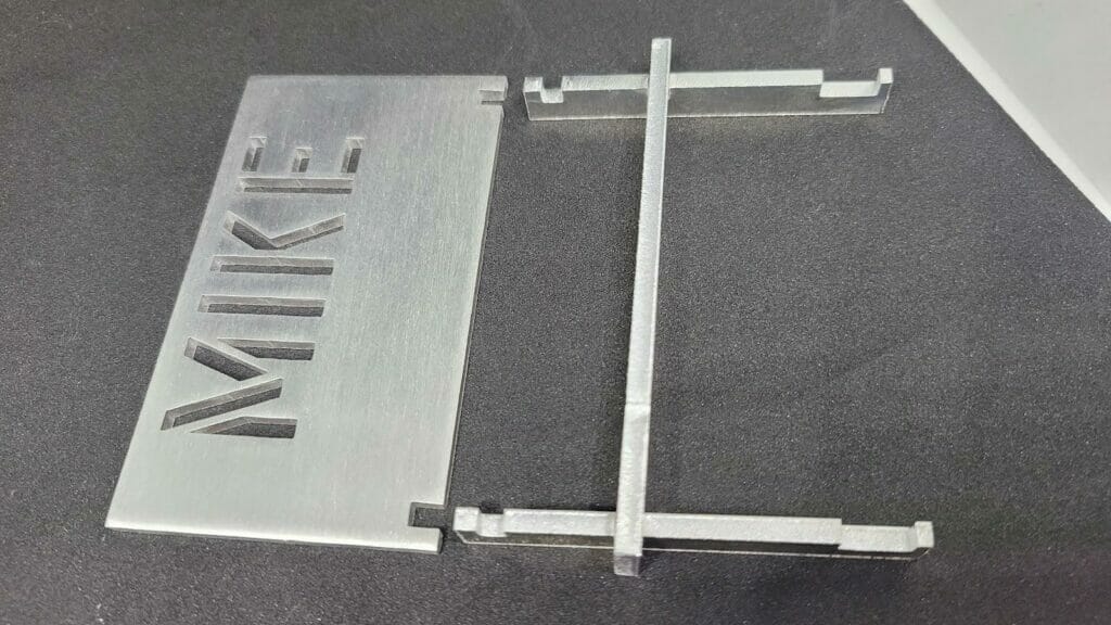
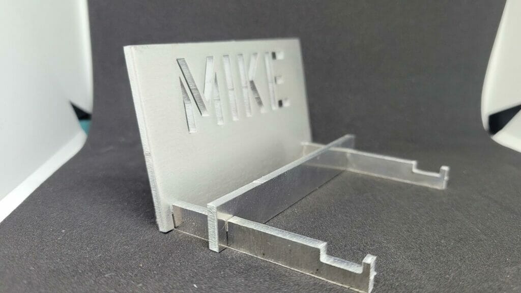
Small-scale, non-structural assemblies can also be designed for assembly by the end-user. The cell phone holder below is designed to be sent to the customer, put together by them, and sit on their desk. The backplate can be customized with your customer’s logo or name.
Stiffeners are often used between channels and bent parts to increase strength. While traditionally a stiffener would be made from a flat bar or structural angle, laser-cut sheet metal can be used and tabbed directly into the parts it will align with. Furthermore, by varying the tab width the part can only be oriented one way. By using varied tab and slot sizes, assembly speed and accuracy will follow. In the following examples, a stiffener is used and has a laser-cut tab at each end of the leg, and tabs extended on the bent flange. This allows for more welding surfaces and a stiffer connection
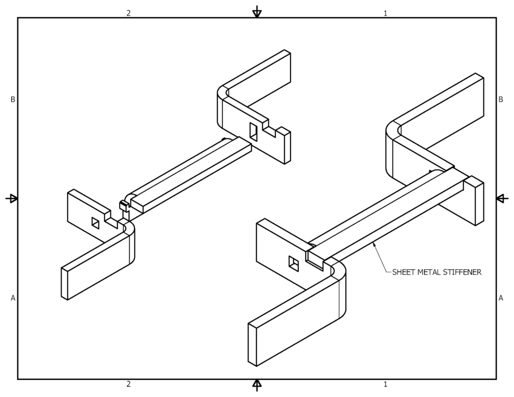
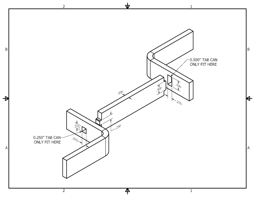

Plug welding can be used at the tabs that fit into the slots and cutouts.


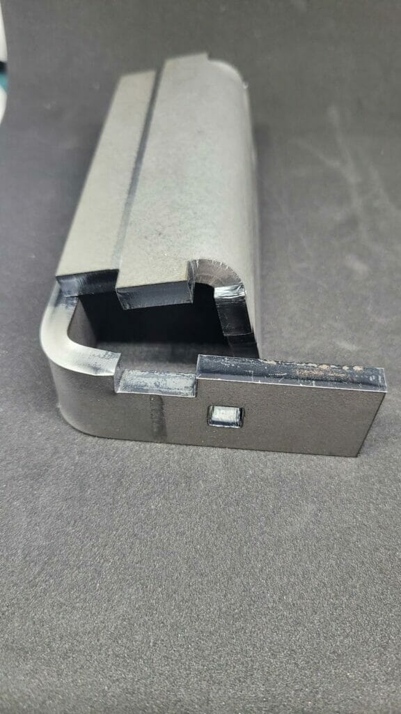
Incorporating slot and tab features into your sheet metal parts increases flexibility, decreases cost during fabrication, and allows for a more streamlined design process.
Please note that the numbers in this article lean on the conservative end and that for large-scale production runs, we recommend testing the sizes first. It’s also important to note that thicker materials can add complexity to the tab/slot design process. Finally, when using tab and slot designs on bent parts, especially between two flanges on the same part, it is important to consider our bend tolerances as well. Please refer to the thickness and bending guidelines for more information on how to work with these variables and how to create better parts for you and your customers.
