Anyone who grew up with a sibling understands what tolerance is: how much can I tolerate something before it becomes a problem. Machining tolerances are no different. Tolerances are effectively how much dimensional error can be tolerated in the part before it creates a problem.
With any machined part, there is some inherent level of error from a perfect cut. Each fabrication technique can have a different level of how precise that cut is. For example, band saw cuts might have a precision of +/- 0.030”, or roughly the thickness of two business cards’ worth of error in each direction. So a 1.000” nominal length cut could be as long as 1.030” or as short as 0.970”. A much more precise process, wire EDM (electrical discharge machining), can commonly achieve tolerances of 0.0001”, one ten thousandth of an inch, or 1/10th of a thou. For perspective, that is 40 times thinner than a single piece of paper!
This article will go over why tolerances are important, discuss tolerance stacking, what GD&T is, and explain some of the most common GD&T symbols.
An Overview of Machining Tolerance
Thickness Tolerance
As mentioned above, every fabrication process has a tolerance. This even applies to the thickness of raw materials used by every fabricator. SendCutSend lists this thickness tolerance on each material, below is a screenshot of the thickness tolerance on ABS plastic, which has a thickness tolerance of +0.007”/-0.006” for 0.125” thick nominal stock.
This means the thickness of any piece of ABS could be up to 0.132” or as thin as 0.119”. Keep these tolerances in mind for any engineering calculations. Normally the amount of deviation is so minor that calculations can be done on the nominal stock. However, for critical applications, or applications with small safety factors, consider using the thinnest thickness for strength evaluation and the thickest for evaluating weight limitations.

Above are the material details found on SendCutSend’s website for ABS plastic. Note that the tolerances vary for thickness tolerance, cut tolerance, and flatness tolerance.
Tolerances of Processes Offered by SendCutSend
Below, the SendCutSend processes most affected by tolerances will be discussed in order from loosest tolerance to tightest tolerance.
Sheet Metal Bending
Sheet metal bending has the loosest tolerance of the services offered by SendCutSend at +/- 0.015” and +/- 1 degree per bend. I.e. if a part has two bends in series, then the total tolerance could stack to +/-0.030”. For perspective, 15 thou is about the thickness of a business card. Sheet metal bending is an economical manufacturing process, allowing the use of affordable sheet metal to get 3D parts. If extremely tight tolerances are required, other manufacturing processes such as conventional milling, can be utilized; though typically at a significant increase in cost per part.


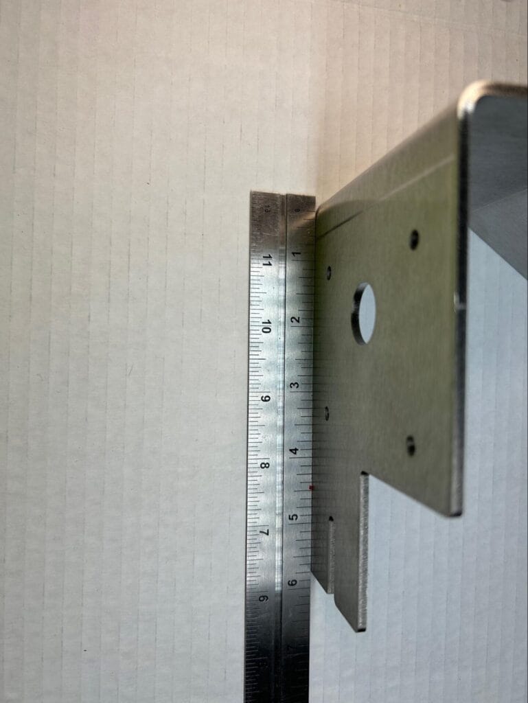
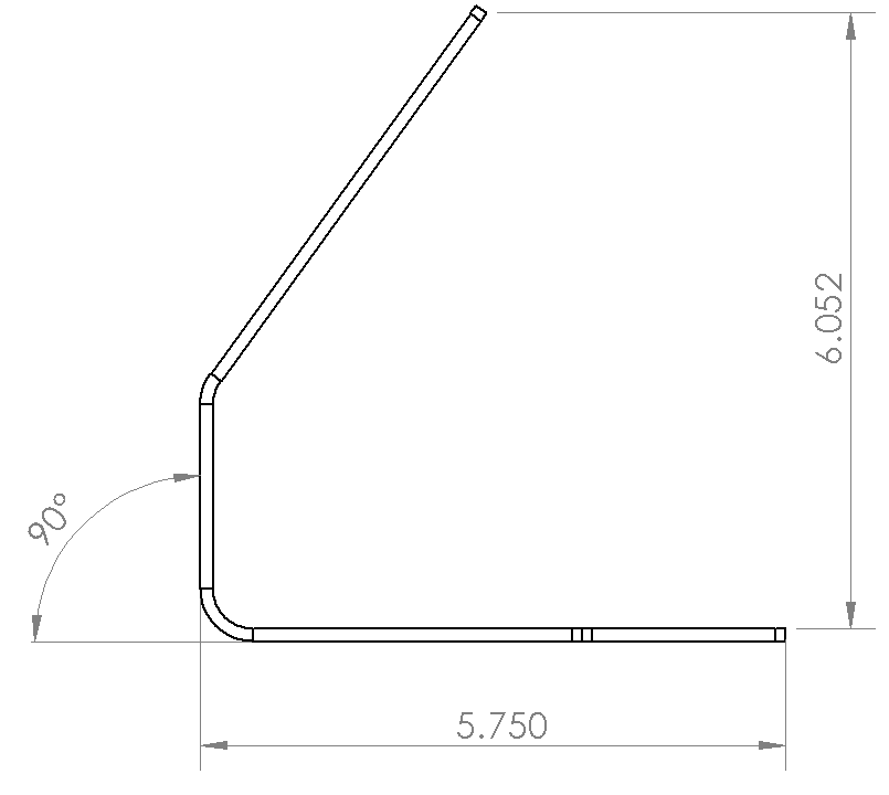
In the images above the bent stainless steel part matches the drawing dimensions. The square cleanly aligns with the front corner, and the base of the part measures 5.750” when the edge of the ruler aligns with the front face of the part.
Waterjet Cutting
Cutting by waterjet typically holds a tolerance of +/-0.009” or roughly the thickness of two pieces of paper. Waterjet is the process we use to cut carbon fiber parts. One thing to be aware of beyond the machining tolerance, is that all waterjet parts will have a small fixturing tab leftover from the machining process. This tab is to ensure your parts don’t move during the manufacturing process, and is easily sanded off in a matter of seconds.
Image of Carbon fiber cover plate

The instrument panel shown above has a tolerance on each measurement to guide the fabricator on how to ensure the part is within acceptable tolerances. Note the dimension vs the drawing is well within the specified tolerance, so this part passes quality inspection.
CNC Routing
CNC routing allows for tight tolerances of +/-0.005”, or roughly the thickness of a single sheet of paper. This 2D process is similar to CNC milling, but more affordable, and with a smaller set of materials available. One thing to be aware of beyond the machining tolerance, is that all CNC routed parts will have a small fixturing tab leftover from the machining process. This tab is to ensure your parts don’t move during the manufacturing process, and is easily sanded off in a matter of seconds.
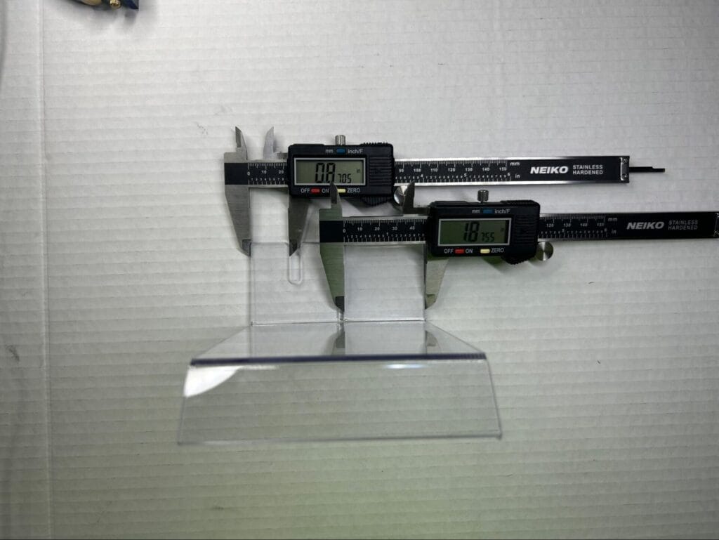
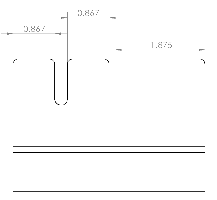
The polycarbonate (aka Lexan®) shown above is well within the stated CNC routing tolerance of +/-0.005” with the left measurement being 0.003” oversized, and the right measurement being within 1 thou.
Laser Cutting
Laser cutting is SendCutSend’s flagship service, and what put us on the map. Much like with the other services, the tolerances can vary based on the material selected. Plastics, like Delrin and wood materials tend to have a tolerance of +/-0.009”. Whereas metals tend to have a tolerance of +/-0.005”. This tolerance holds true for our super hard AR500; as well as softer materials like mild steel or 304 stainless.
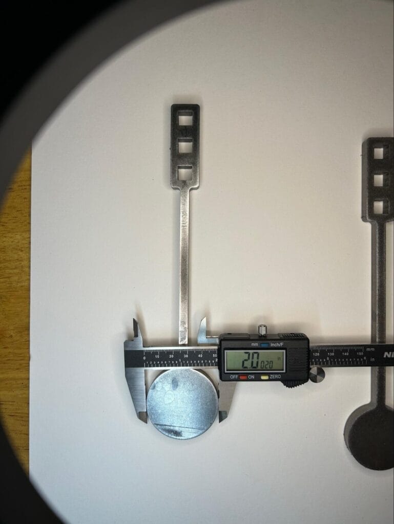

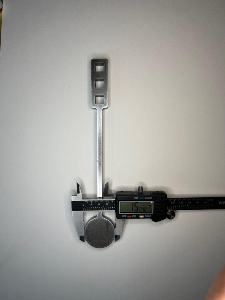
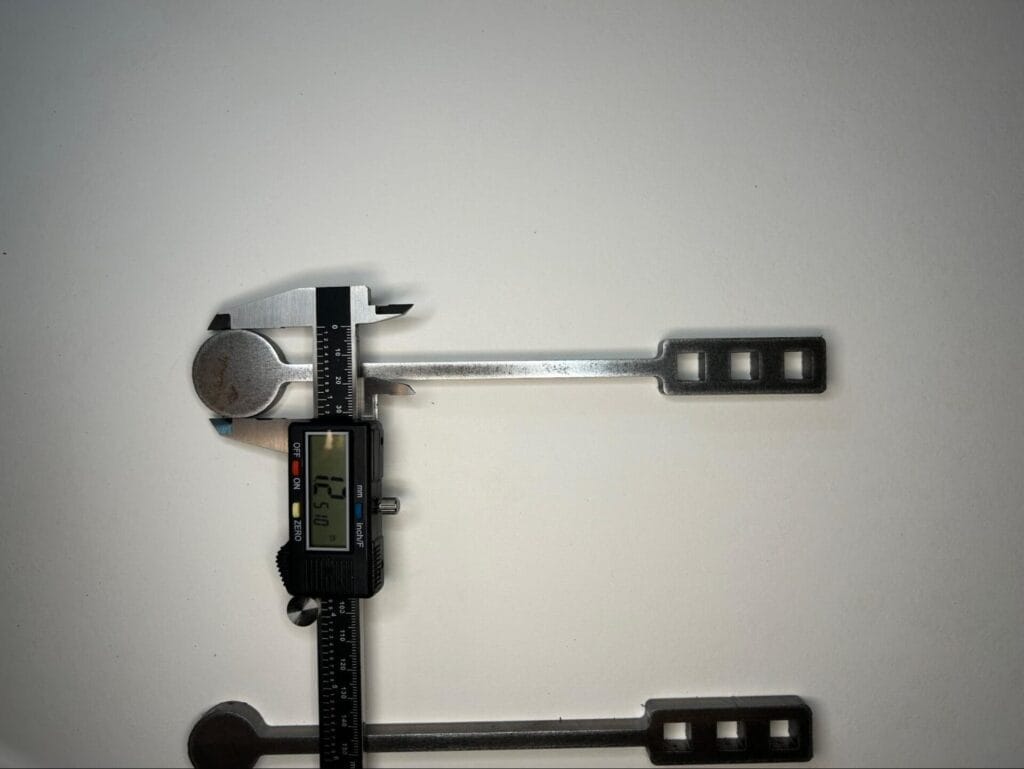
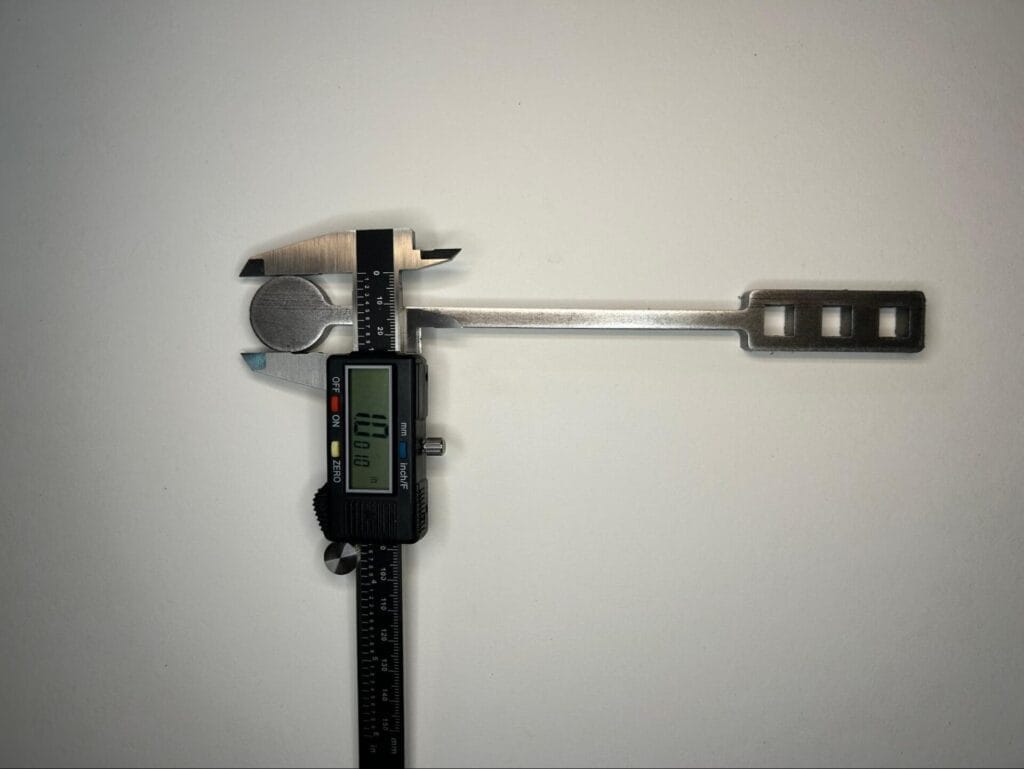
Above, AR500 parts are measured as compared to the drawing. Note that the +/- 0.005” tolerance holds true regardless of feature size. Average tolerance is within 1.5 thou of nominal despite a 2x difference between largest and smallest feature.

304 stainless steel parts are measured as compared to the drawing. Despite material differences in strength, hardness, size, and other properties, the +/- 0.005” remains the same.
Coatings
While coatings aren’t traditionally thought of as a fabrication process with tolerances, they can have a significant impact on the overall dimensions of a part. Depending on the process, the thickness added can be substantial. Powder coating for example can add up to 10 thou (0.010”) to a part’s overall thickness! Below is a list of the coating services currently offered by SendCutSend. For more information on the differences, see our post on Coating Comparisons.
Nickel Plating adds 0.0002” per side
Zinc Plating adds 0.0003” per side
Anodizing adds 0.0002”-0.0009” per side
Powder Coating adds 0.002”-0.005” per side
Tolerance Stacking
Tolerance stacking is the summation of tolerances from multiple parts and how they interact. For instance, if an assembly has 3 critical parts that must fit together, each of them must fit regardless of if any combination of the maximum or minimum tolerances are hit for each interacting feature. What starts as a small tolerance can grow to be fairly large when multiple tolerances stack together. In the example below, there is a locating pin feature that aligns three plates together. There are multiple tolerances that must be accounted for in order for the parts to fit together properly: the location of the pin, the size of the pin, the diameter of the green plate’s thru hole, the position of the green plate’s thru hole, the diameter of the red plate’s thru hole, the position of the red plate’s thru hole. Keeping tolerance stacking in mind will maintain proper design functionality, while also allowing for proper tolerances to be specified.
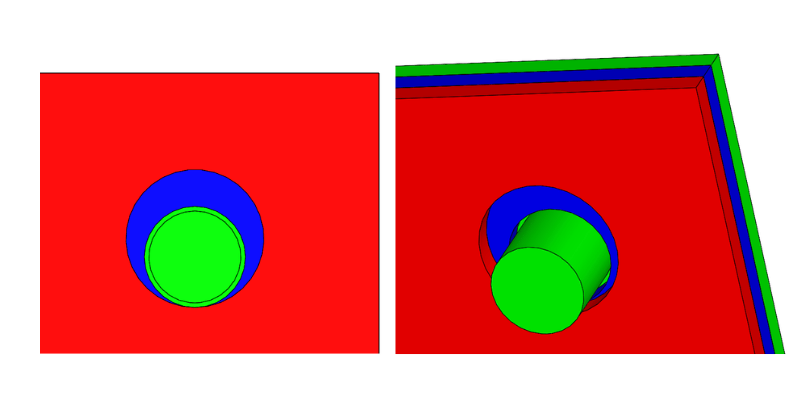
In the above image it can be seen that the red plate has a hole that is not properly centered on the pin, but due to the oversized hole, the pin still fits through both plates.

However in the second example above, the yellow plate has a hole that is slightly too low, which pushes the pin beyond what the oversized hole in the red plate can accommodate, thus the pin cannot fit through both plates due to the tolerance stacking, and it interferes/passes through the red plate.
Selecting a Proper Machining Tolerance
Like most things in the design world, selecting the proper machining tolerance is about balance. It would be easy to just select the tightest tolerance offered by a fabricator for every part. However doing so would be very expensive, and likely increase the schedule required to obtain parts. The risk in holding extremely tight tolerances is that the chances of parts being scrapped goes up drastically as the tolerance gets tighter. A single mistake could cause a part to become useless if all the tolerances are overly strict. Scrapping a part costs extra money to the fabricator, as well as slows down the entire fabrication process. These extra costs and time are reflected in shop lead times as well as the expense of the part itself when it is quoted. Therefore it is important to maintain the tolerances required to ensure proper function of the part, but no tighter than necessary.
Geometric Dimensioning and Tolerancing (GD&T)
What is GD&T?
GD&T stands for geometric dimensioning and tolerancing. It is a system to convey what the dimensions should be, as well as what tolerance is allowed to still be an acceptable part. These measurements and tolerances are communicated through an internationally recognized set of symbols. These symbols are managed by the American Society of Mechanical Engineers (ASME) in their standard Y14.5.
Why is GD&T used?
GD&T is used to convey design intent to the fabricator. Think of it as an efficient language that allows a complex description of inspection processes with a single symbol. For example, the profile tolerance conveys that a part must be machined to within the declared tolerance everywhere along the profile as defined in the CAD.
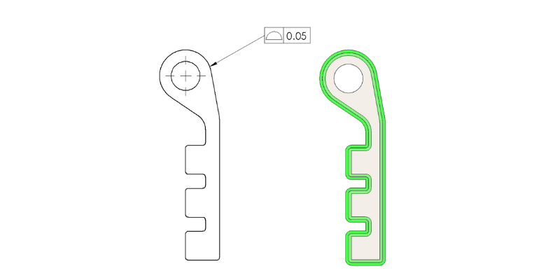
The above callout is indicating that the surface of the part must be within 50 thousandths of an inch of the nominal CAD. This is visualized by the green border around the part on the right, indicating the acceptable tolerance zone for the part.
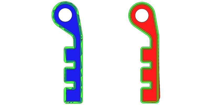
In the above example, the blue part on the left is very roughly cut, but it is within the surface tolerance specified, thus it passes inspection. The red part on the right however fails inspection because it goes out of the tolerance zone in the lower right corner. This highlights the importance of being intentional with which tolerances are specified
Common GD&T Symbols and Their Meanings
Datums
Datums are reference features where a tolerance will be measured from. It conveys what the most critical reference is. Depending on the datums and dimensions used, a certain measurement might not be considered at all to determine if a part passes inspection. Keep this in mind when defining datums and measurements.
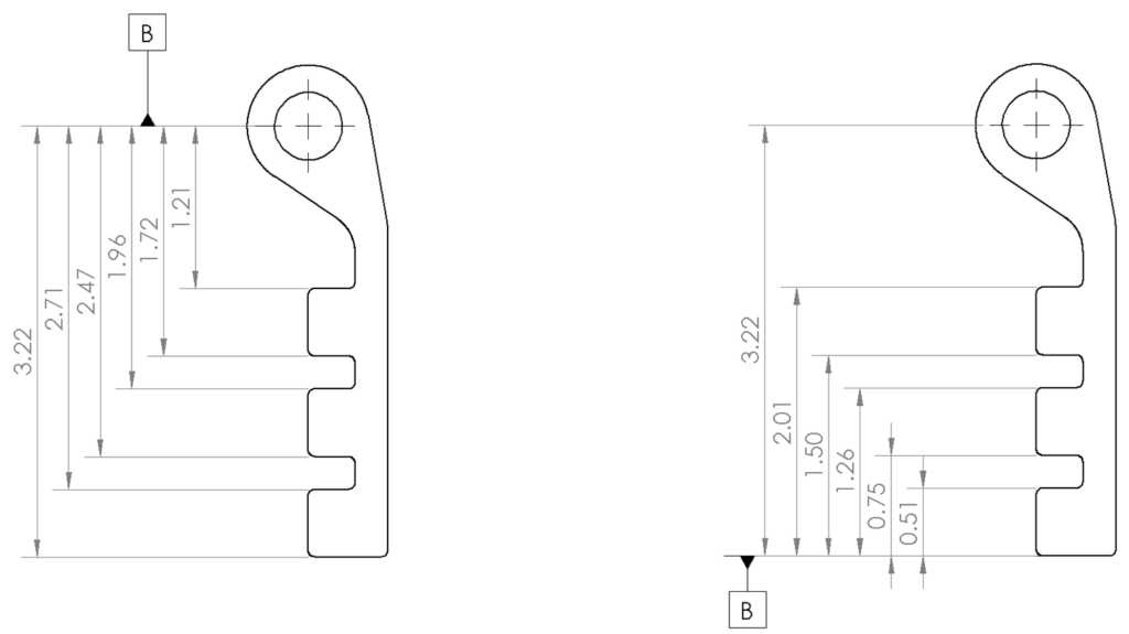
In the example above, the key shaped piece is drawn two separate ways, with the circular feature as the datum, and with the flat end as the datum. The circular datum conveys that distance from the circular component is the most critical for proper function. The flat end datum conveys that dimensions relative to the flat end of the part are more important.
Basic Dimension
A basic dimension, a dimension enclosed with a box, is the ideal dimension desired, or to phrase it another way, the target dimension. The feature tolerance is based on this basic dimension. For example, the position tolerance of a hole is a cylindrical feature, with the center at the location indicated by the basic dimensions, oriented normal to the first datum in the feature control frame (aka primary datum feature), and with a diameter equal to the feature tolerance value. In the image below, the green dotted circle indicates the area where the center of the actually drilled hole must fall. If the center is outside that green dotted line, then that hole is out of tolerance.
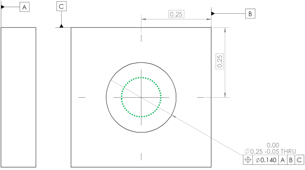
A 2D drawing of a hole in a plate with the acceptable hole center position highlighted with a dotted green circle. Worth noting is that a 0.140” diameter positional tolerance is approximately analogous to +/- 0.050” in coordinate tolerancing.
Position (AKA “True Position”)

Position tolerance is a fairly complex symbol in GD&T, but it is also one of the most commonly used. Position indicates a volume that your feature must be located within.This volume is centered around the ideal or “true” position indicated by basic dimensions. The shape of the volume varies with the shape of the feature. For example, a hole is a cylindrical shape and has a cylindrical position tolerance, while a spherical feature has a spherical position tolerance. A rectangular feature such as a square slot, would also have a rectangular positional tolerance.

In the image above, a hole has been drilled that is clearly not perfectly normal to the bottom face of the plate. However, it is still within the green cylinder representing the acceptable position tolerance, so it passes inspection.
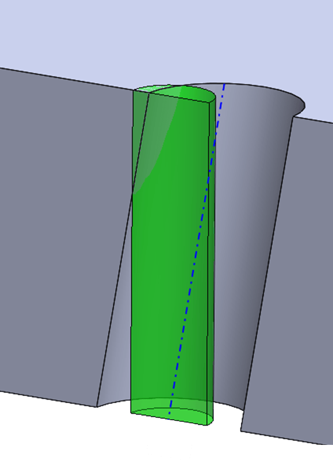
The above example shows how the hole has violated the tolerance zone at the top. Even though the bottom of the hole is precisely at the position indicated by the basic dimensions, the perpendicularity of the hole makes it fail the tolerances specified in the position tolerance.
Material Condition Modifiers aka “Bonus Tolerance”
Regardless of Feature Size (RFS)
Regardless of feature size is exactly what it sounds like, the tolerance stated is the tolerance allowed regardless of the size of the feature. This is the default for a tolerance; so if there is no circled letter next to the tolerance number in the feature control frame, then a fabricator knows that tolerance is the same regardless of how far from nominal the feature measures.
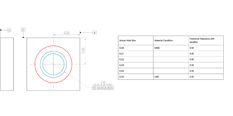
The above drawing shows a tolerance with no modifier, or RFS. The red circle indicates the outer bounds of where the hole edge can fall while still being in tolerance, whereas the blue circle indicates the inner bounds. The table to the right shows the positional tolerance relative to actual hole size, note how tolerance is the same for all hole sizes.
Maximum Material Condition (MMC)
Maximum material condition, a circled “m” shown above, is when a feature would make a part heaviest, i.e. have the most material in it. For an external feature, such as a pin, that means a larger diameter; however for an interior feature, such as a thru hole or a slot, that means the smallest diameter. This modifier is often used on clearance holes because it is “bonus tolerance”. As the hole size gets larger, the tolerance allowed gets larger. This is most often used for clearance holes/bolt holes.

The above drawing shows a tolerance with the maximum material condition modifier, MMC. The red circle indicates the outer bounds of where the hole edge can fall while still being in tolerance, whereas the blue circle indicates the inner bounds. The table to the right shows the positional tolerance relative to actual hole size. Note that when the hole size is at MMC condition, or 0.20” hole diameter, the tolerance matches the number in the drawing, and you get “bonus tolerance” as the hole size gets bigger.This modifier ensures a minimum clearance is maintained.
Least Material Condition (LMC)
LMC, a circled “L” as shown above, is when a feature makes a part the lightest, i.e. has the least material in it. For an external feature, such as a pin, that means a smaller diameter; however for an interior feature such as a thru hole or a slot, that means a larger diameter. This is a fairly rare modifier. The primary use case is when a feature is close to an edge, like a bolt hole is close to the edge of a part. It is most often used when the designer wants to preserve a minimum wall thickness for that feature. The LMC modifier could be used so that as the hole gets smaller in diameter, you get some amount of “bonus tolerance”, which would preserve the minimum wall thickness.
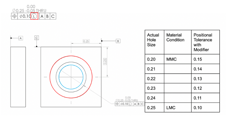
The above drawing shows a tolerance with the least material condition modifier, LMC. The red circle indicates the outer bounds of where the hole edge can fall while still being in tolerance, whereas the blue circle indicates the inner bounds. The table to the right shows the positional tolerance relative to actual hole size. Note that when the hole size is at LMC condition, or 0.25” hole diameter, the tolerance matches the number in the drawing, and you get “bonus tolerance” as the hole size gets smaller.This modifier ensures a minimum hole to edge thickness is maintained.
Machining tolerances refer to the allowable error between an as fabricated part and the nominal dimensions specified on a drawing or CAD file. GD&T stands for geometric dimensioning and tolerancing, and is a standardized set of symbols and drawing practices used by designers to communicate design intent to fabricators so the fabricators can manufacture parts acceptable for the designer. Machining tolerances have come a long way in recent years. Here at SendCutSend we do everything we can to ensure your parts are as precise as possible at the best possible price. If you have any questions, feel free to reach out to us at support@sendcutsend.com. If you’re curious how else we can help, check out this brief article: What SendCutSend can do for you. When you’re ready, upload your design and get instant pricing today!
If you are new to SendCutSend, here’s a handy step-by-step guide on how to order parts from us: How to Order Parts from SendCutSend (spoiler alert: it’s super simple and intuitive to order from us)
FAQs
- What is GD&T?
- GD&T stands for geometric dimensioning and tolerancing and is a set of symbols and standardized practices used to convey information on an engineering drawing used to fabricate parts. It is managed by the American Society of Mechanical Engineering (ASME) though it is used in many countries.
- What is tolerance stacking?
- Tolerance stacking is when multiple parts must fit together, their combined tolerances (or tolerance stack) must be taken into account. I.e. if three plates must be bolted together, then the total tolerance between the three plates must be tight enough that the holes still align enough for a bolt to fit through them.
- What is machining tolerance?
- Machining tolerance is the allowable deviation from the nominal dimensions specified on a part, or how far off a measurement can be from perfect before it becomes a problem.


