One of the great things about Rhino3D is its ability to create complex shapes and designs. These designs can be used to create photo-realistic renderings that rival software substantially more expensive than Rhino3D. That complexity, however, can be an issue when you want to use the designs to create laser cut parts so it’s important to know how to reduce nodes in Rhino3D.
Complex designs, especially organic shapes, tend to be point-heavy and can create issues when the design is exported to DXF. Luckily, there are a few simple ways to combat this issue. One is to make sure that you are exporting your design according to the guidelines in our “Creating a Rhino3D Export to DXF” article, and another is to convert the complex curves in your design to arcs. Follow the steps in this guide while working with your own design to simplify your cut lines and reduce the number of nodes to ensure a successful cut!
What are nodes and why should I care about them?
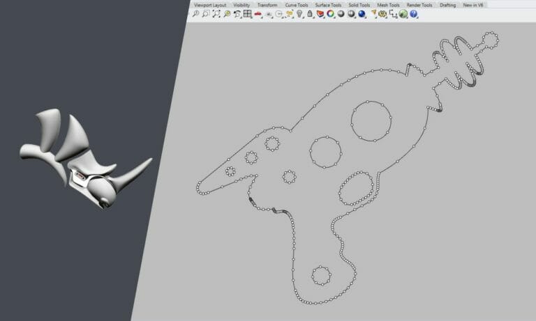
“Node” is essentially another way of saying “point.” Our lasers will follow your design, point-by-point, whether you have just enough points or far too many. If you have too many points, you will see quality issues that are otherwise avoidable. On thinner materials, you’ll see thin, vertical marks on the edges of your parts, increased dross, and potentially reduced accuracy due to the laser remaining in one area longer than it should with many nodes in close succession. Excessive points in thin material can also cause your part to warp.
On thicker materials, you’ll see deeper, more pronounced witness marks along the edges along with dross and reduced accuracy due to prolonged laser dwell.
Our automated system is unable to process files with excessive nodes, and the laser software will reject files like this because it won’t be able to cut them. Additionally, files with excessive nodes are oversized and can bog down your software, slowing down your overall design time.
All in all, it’s best to avoid excessive nodes because we will send your design back to you and ask you to remove the extra points before we can machine your parts. So to get your parts cut and shipped faster, the best thing to do is remove those extra nodes before you send the file to us!
When should you convert your design?
Because the process is so quick, we recommend converting any design that you create before exporting the file for quoting. Converting becomes especially important when organic shapes are involved, or if you are creating a substantially smaller version of a much larger design. In any scenario, fewer points mean you’ll be getting better-looking parts.

You can see the points in your design by selecting your geometry and then clicking on the points icon.
How does Rhino3D convert my design?
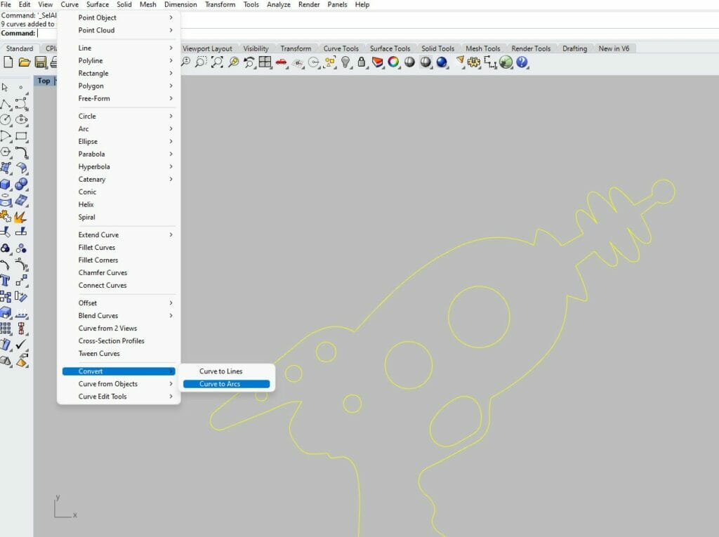
There are several ways to change the point structure of your design from within Rhino. We recommend the “Convert to Arcs” command within the “Curve” menu. This command converts your complex curves into simple arcs to reduce the number of points. The design is modified by a predetermined tolerance in order to do this, so it is important to take this into consideration. We’ll show you the changes made by this tolerance later on in the article.
Step 1: Convert Your Geometry
Select the geometry that you are going to convert.
From the “Curve” menu, select the “Convert” sub-menu, and select “Curve to Arcs.” The conversion to arcs is key for reducing nodes in Rhino3D. This will bring up a series of options in the control bar.
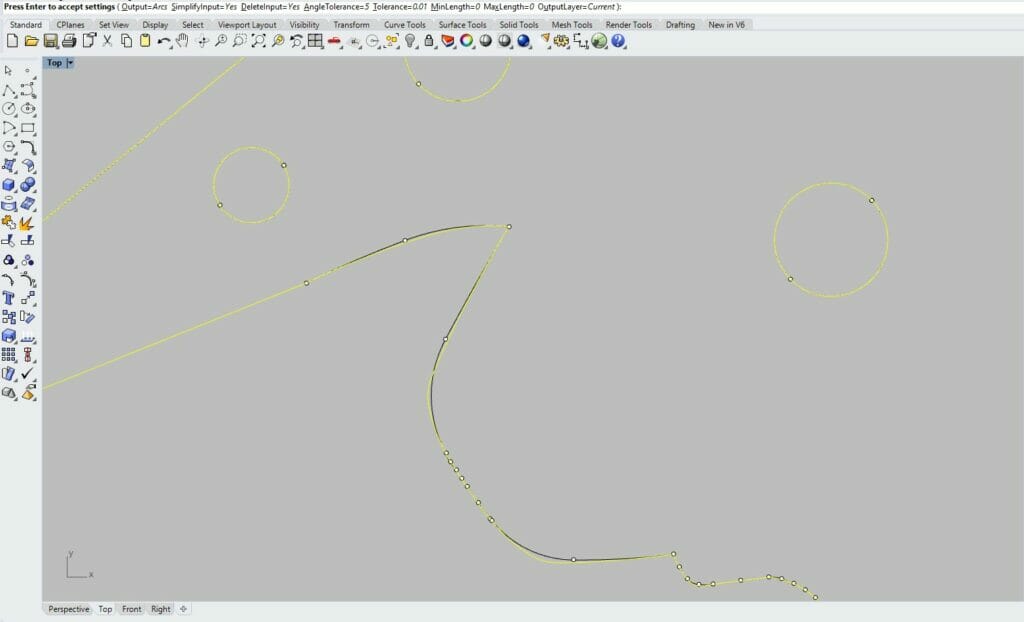
The options in the control bar should look like this:

The options should be set as follows:
- Output = Arcs
- SimplifyInput= Yes
- DeleteInput= Yes
- AngleTolerance = 5
- Tolerance=0.01 (this is for a drawing set up in inches, the tolerance should be .254 for a drawing in millimeters)
- MinLength = 0
- MaxLength = 0
- OutputLayer= Current
Step 2: Confirm the reduced nodes in your design
Before hitting “enter” to complete the task, zoom in on your design and see if the changes are acceptable to you. The original drawing will be highlighted, and the revised version will be black.
The difference between your original design and the new revised one is determined by the tolerance setting. Again, we recommend setting your tolerance to .01”, the thickness of an average index card. If you are drawing in millimeters, we recommend setting the tolerance to .254. Changing this too drastically can affect the integrity of the design and reduce the nodes to the point of being unable to recognize the original design.
After you’ve confirmed the difference between the original and the modified version of your design and you’re comfortable with the changes, hit “enter” to complete the process.
Congratulations! Now you know how to reduce nodes in Rhino3D and you’ve simplified your design and made a file that is much more suitable for processing at SendCutSend!
Step 3: Export your file
For a design made with Rhino3D, you will need to export it as a DXF file in order for us to process it. For step-by-step instructions on how to export a DXF file from Rhino3D, read through our Rhino3D guide.
As always, make sure your design fits within the guidelines for each service of ours that you intend to use. It’s best to check these guidelines against your design before you create your export to avoid having to make changes and then create a new export.
SendCutSend and Rhino3D
When choosing a software to use when designing parts for us to machine, you should ultimately use one of our Recommended Software. We don’t recommend using Rhino3D if it can be avoided because it’s likely to produce inconsistent results, as shown by the issues with high node counts we’ve discussed in this article. There are several free software options we recommend alongside the professional software with a paid subscription base, including QCAD, Fusion, and Inkscape.
Be sure to check the Tutorials category of our blog often to find new tips for using these software in your own workflow, and sign up for our blog subscription to get the latest articles emailed to you every Friday!
