
Nesting, an integral aspect of modern manufacturing, stands as a linchpin for efficiency and resource utilization within various industries. Often obscured in the complexity of production processes, nesting involves the arrangement of different parts on raw material sheets, seeking to optimize the use of available resources during the machining process. This process is a cornerstone of material optimization, providing manufacturers with the means to minimize waste, reduce production costs, and maximize the utilization of raw materials. By strategically positioning shapes and sizes within a given space, manufacturing efficiency is significantly enhanced. Moreover, the implications of nesting extend beyond mere operational improvements, playing a vital role in sustainable manufacturing practices and the reduction of environmental impact.
Understanding the nuances and significance of nesting within the manufacturing landscape is crucial for businesses and individuals alike aiming to save time and money in their manufacturing projects. We’ll explore the importance of nesting in manufacturing, delving into its multifaceted benefits and going over some best practices for setting up files which include nested shapes.
A Step Back: What Does “Nesting Parts” Mean?
Nesting is the process of laying out the designs to be cut out of a flat piece of material in a way that minimizes the amount of material used and outputs the best possible result from the machining process. Nesting also allows machines to cut parts faster as nesting tools can help determine the shortest distance between the final cut of one part and the beginning cut of another, shaving valuable time off of the machining process. This might be achieved by placing unrelated designs inside of the negative space of other designs or skewing the angle at which the designs are cut to optimize the used material.
Although the machining processes we use here at SendCutSend are cutting edge technology, the term “nesting” and the algorithms used to nest parts have been around for almost 100 years, before machining processes were even computer controlled. In the early half of the 20th century, optimizing machine time and material used was vital to wartime manufacturing all over the globe. With thousands of the best machinists working to solve the problems that arose with rationed materials, nesting became common practice. With the time and money it saves, there is little surprise that machine shops today continue to use nesting for their 2D machining.
Why Is It Important to Nest Parts?
It’s important to understand the value nesting has in the machining process whether you are ordering parts or making them yourself. Understanding exactly what’s happening in the machine shop while your parts are being made can help you make an informed decision about the materials and thicknesses you use, as well as the designs you make and ensure they’re optimized for the machining process.
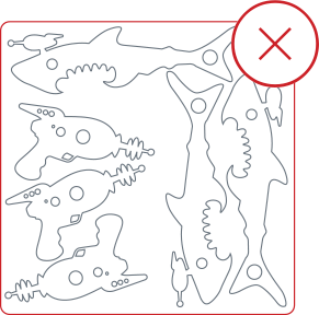
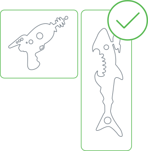
Alongside this, it’s equally as important to know that here at SendCutSend, we do all the necessary parts nesting on our end. We work hard to ensure that your parts are available at the best possible price and machined as quickly as possible, and one of the ways we do that is through our highly optimized nesting process. To help us get your parts to you quickly and at an affordable price, do not prenest your parts. Upload only one part per file and adjust the quantities during the ordering process, and the instant pricing that you see will take nesting savings into account. If you upload a file that has 100 parts on one sheet of material, you may be overpaying for the material used and the time it will take to cut them. Sending us only one part per file will actually save you time and money!
Nesting Files and Creating Bridges for Nested Shapes
In certain designs, you may end up with negative space that’s integral to your design but isn’t connected to any other part of the laser cut piece. We call these “nested shapes,” and because they are different from nested parts, you need to know how to design for them so they won’t be lost to the laser cutting process.
The steps included in this process are some best practices for designing with nested shapes in mind, and can be taken into account if you must send nested parts to us for machining. Do keep in mind that if you have to nest your parts, the nested files must still fit within our requirements. And due to the nature of the added complex geometry and time necessary to process nested files, your lead time may be lengthened and the cost per part may be higher than if you are able to send us individual part files.
Nested shapes (shapes inside shapes) need to include bridges the same way that text needs to have included bridges. Let’s say you wanted to laser cut a donut from your metal sheet. Once the outer circle has been cut out, there is nothing left to cut the inner hole from. You need something to connect or hold onto that inner circle.
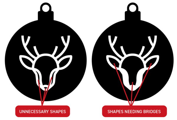
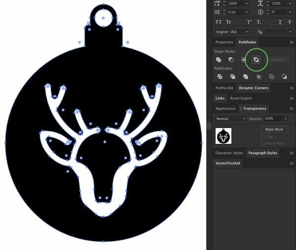
For example, let’s say you’re designing some Christmas ornaments. In the example on the left below, “good cuts” or shapes that are safe from being lost in the machining process have been highlighted in green. The “lost cuts,” which are outlined in red, have no connection to the outside shape and therefore will be lost. We need to add connection points to these shapes.

Step 1: Remove Unnecessary Geometry
When adding bridges, you want to make them look like they are part of the intended design and not just thrown on as a quick fix. You’ll also want to keep in mind things like your material thickness and design complexity. Lines and shapes should not be less than 1.5x your material thickness.
Let’s first remove any small and unnecessary shapes.
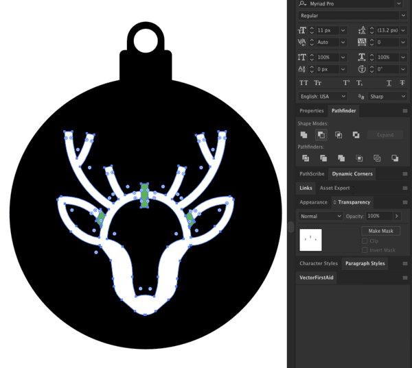
Step 2: Adding Bridging
Now you need to add bridging. Draw a shape where you want your bridges to be placed. Selecting both the shape of the reindeer and my bridge shapes, you’ll want to subtract the shape of the rectangle from the design underneath. There are several ways to do this, so be sure to check out our tutorials for adding bridging in both Inkscape and Adobe Illustrator. The method for this will change depending on what design software you use.
Step 3: Remove Empty Shapes
You’ve now added bridges to your design. View your design in Outline mode (available in both Inkscape and Adobe Illustrator) to make sure no empty shapes have been created using the Minus tool. These will need to be removed before proceeding.
Step 4 (Optional): Adding Fillets
Fillets are just rounded edges to prevent sharp corners. This is easier to manufacture for many machining methods due to rounded tooling, and makes it easier to remove your shapes once cut. In any design tool, there is an option for rounding the edges of the path. It’s usually a click-and-drag tool that rounds the edge the more you drag. Find a setting you like and save your design.
Step 5: Exclude
Once the shape you intend to cut out looks the way you want it, the last thing to do is remove it from the larger piece of material. Selecting both paths, use the Exclude tool in the Pathfinder (AI) or Path (Inkscape) palette.
That’s it!
Getting Your Nested Files On Point for SendCutSend
When it’s done by the pros, nesting saves you time, money, and effort in the end. We make sure the layout of your parts on the material is optimized to give you the best possible price and minimize the amount of time the sheet spends on the machine. This is why we prefer if you send us single parts in each file and leave the nesting to us. However, if you need to nest your parts for a specific reason, just make sure your parts fit within all our nesting guidelines. Nested files do still need to fit within our material minimum and maximum sizes, and cuts need to be given the same adequate spacing as with single part files.
If you have other questions about how to prepare your files for laser cutting, we have plenty of great tips on our blog. You should also be sure to go through some of our tutorials for the specific design software you use. Whether it’s vector-based or CAD software, each program has its own unique quirks and we’ve created tutorials for dozens of them so you can create high quality files every time.
Once your files are ready for laser cutting, just upload them and get an instant pricing today!


