Solidworks is one of the most popular CAD programs used in the industry of metal fabrication and engineering. It can be incredibly helpful to your design process, however, there are a few things to be aware of to avoid problems related to designing for sheet metal fabrication. By understanding 5 of the most common issues when designing sheet metal using Solidworks, you can avoid these pitfalls to make sure that your Solidworks designs are manufacturable and compatible with laser cutting methods.
1. Not Using the Sheet Metal Tool
The first common issue when designing sheet metal using Solidworks is not using the sheet metal tool. While designing 3D parts in Solidworks can be a straightforward process, designing for sheet metal is more complex due to the inherent geometrical changes that happen to the part during fabrication, particularly during sheet metal bending. When sheet metal is bent and formed using processes such as press brake bending, the inside surface of the bend experiences compression, and the outside surface experiences elongation. It’s important to understand this because this has implications on what the appropriate lengths of the un-bent material should be, and where the bend lines should be located, in order to compensate for the permanent deformations resulting from bending.
The Solidworks sheet metal tool automatically takes into consideration these geometrical changes, provided that you feed it necessary sheet metal parameters that describe the geometry you are working with. Some of these parameters include K-factor, sheet thickness, and bend radius. To learn more about K-factor and the mechanics of sheet metal bending reference Our Guide to K Factor in Sheet Metal Bending.
Avoiding the use of the sheet metal tool will result in inaccurate placement of bend lines, and incorrect overall dimensions of laser cut parts. The bends must use SendCutSend’s bend radii and K factor specifications for the material of choice. To understand which specifications to use, reference our Sheet Metal Bending Calculator. To learn more about how to use the sheet metal tool and where to place bend lines in your Solidworks part, visit our Guide to Solidworks Sheet Metal Bending – SendCutSend
2. Selecting The Wrong Bend Line Placement
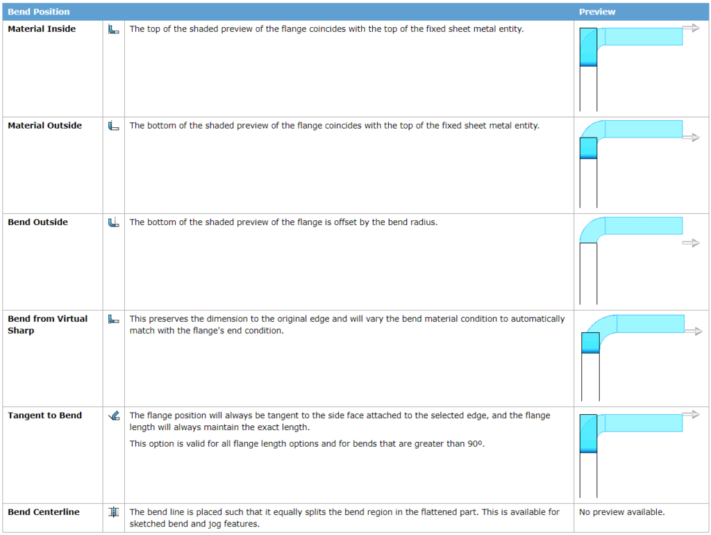
Within the sheet metal tool, Solidworks gives you the ability to choose from several bend line position types. These different bend line positions influence flange and base lengths of the resulting part. Therefore, it is important to select the right one so that the final dimensions of your manufactured parts are correct.
Select “Bend Centerline” when using SendCutSend bending services. This is the only one you need to use for any parts made through SendCutSend. During the bending process, the die contacts the part at this bend line and follows through to create the bend at that location. Namely, the bend occurs at the specified bend line.
Other bend positions result in varying positions of the bend with respect to the bend line. The table below briefly describes the different bend positions offered by the Solidworks sheet metal tool.
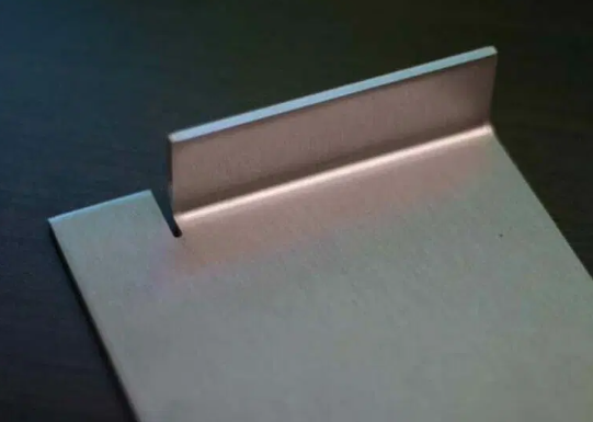
3. Bend Reliefs Not Being Added
Bend reliefs are crucial in sheet metal bending to prevent material distortion and ensure accurate bends. These reliefs are small cutouts or clearances strategically placed at the edges of the bend area. They help distribute the stress evenly during bending and reduce the likelihood of cracks, wrinkles, or material thinning. Without bend reliefs, the material tends to buckle or deform unevenly. In essence, bend reliefs facilitate smoother and more precise bending, leading to higher-quality sheet metal components.
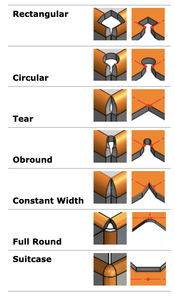
When designing in Solidworks, you can create bend reliefs in the part itself either by sketching them manually and removing material, or using the automatic bend relief generator. If you decide to sketch in bend reliefs without the generator, make sure to adhere to the general design guidelines for bend reliefs.
If you want to use the automatic bend relief generator (a very useful CAD tool included in Solidworks), make sure that you have already been using the sheet metal tool to create your part in Solidworks. The following figure shows the available types of bend reliefs.
4. Not Correctly Exporting Bend Lines
For parts you intend to use SendCutSend’s bending services, it is best to use the Flat-Pattern feature of Solidworks to export the part files in DXF format. The Flat pattern is the shape of the material before any bends are made, and it includes the locations of all the bend lines in the part.
Right click the “Flat-Pattern” feature in the design tree and select “Export to DXF/DWG”. This brings up the DXF output window. Export using the sheet metal option, along with geometry and bend lines. You can learn and try this with a more in-depth explanation in our guide Exporting to DXF from SolidWorks.
Note: Prior to SolidWorks 2022, SolidWorks would put all bend lines into a layer called BEND. In SolidWorks 2022, this default was removed and bends now need to be mapped into flat files by the user. To do this, you need to enable custom mapping. Visit this article to learn how to export in those cases: Mapping Bend Lines in SolidWorks.
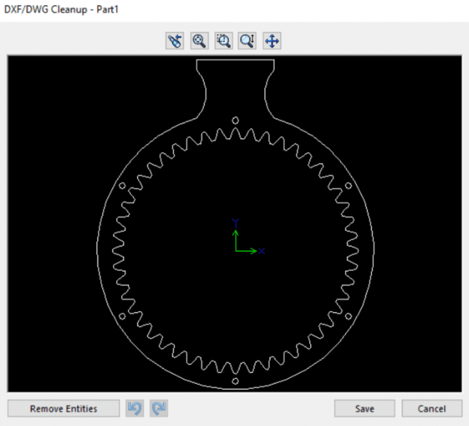
5. Construction Lines Left in DXF File
Depending on which version of Solidworks you may have, sometimes construction lines are left in the DXF file. Thankfully, the DXF export window has a feature called “Remove Entities” in the lower left hand corner of the window (see image below). Select the entity you want to remove, and then click on “Remove Entities”. Your DXF files should only contain the outline of the flat part, and bend lines.
CAD Resources
SendCutSend offers many resources that explain in depth how to use Solidworks and other CAD programs in efficient, effective ways. By understanding how to use these tools properly, you will be able to easily and seamlessly make your designs come to life through the services offered by us here at SendCutSend. Browse through our blog CAD Tutorials for more resources like this one.
