Creating text in a CAD (Computer Aided Design) program is a useful feature that enables laser cut designs to have letters, words, and numbers to be cut into the stock material. Since CAD programs can generate DXF files for laser cutting machines, incorporating text directly into the sketch allows for an easy way to create extrudes in 3D CAD that translate into text inside the DXF file.
This article will describe how to create text in SolidWorks CAD program.
Creating Text
In SolidWorks, text is created on a “Centerline”. This centerline can be placed on a pre-existing object, or on its own. In the example below, a 3D plate is already created, and a centerline is placed on one of the faces of the plate.
Here’s how to create a centerline:
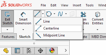
- Navigate to the line button in the design ribbon at the top of the screen
- Select the downward pointing arrow. “Centerline” appears as the second option
- Select “centerline” and draw the line in your desired location
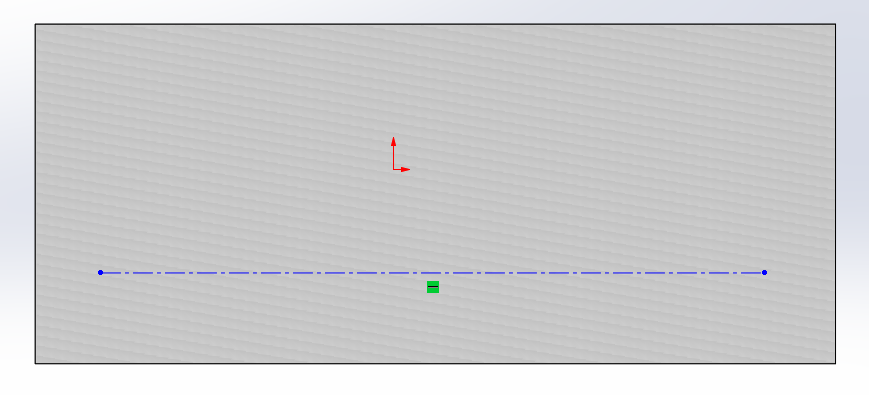
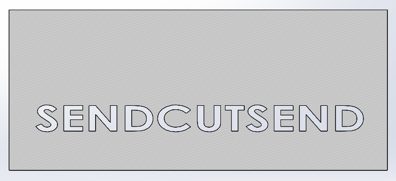
The figures below show the 3D plate with the centerline on its front face.
After the centerline is drawn:
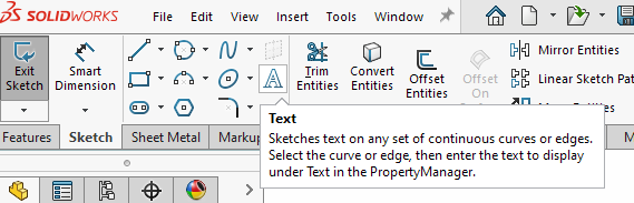
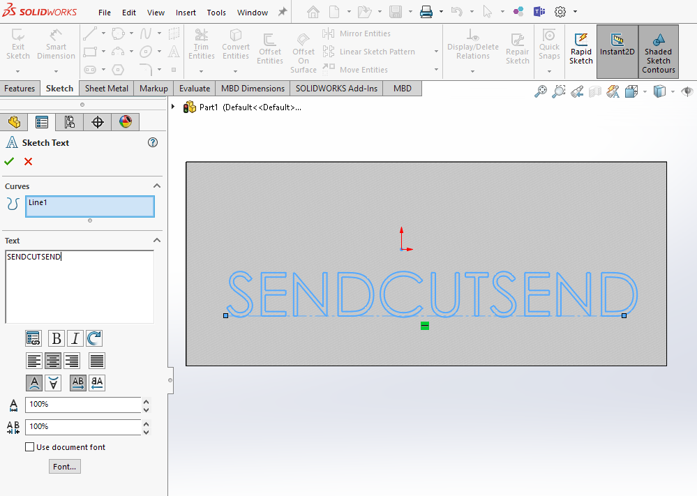
- Select the “Text” button in the design ribbon at the top of the screen. A new box appears over the design tree towards the left of the screen.
- Select the centerline such that it appears under the “Curves” box.
- Type in the desired text into the “Text” box. The text will appear on top of the centerline. Below the text box you can find many optional features that allow you to edit the text size, font, and orientation.
Modifying Text
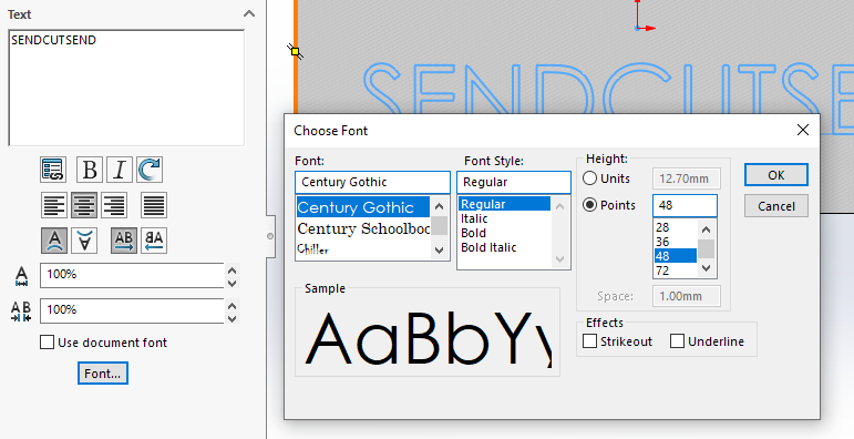
You can modify the text by selecting different icons located underneath the text box. These include bolding, italicizing, and re-orienting. To get access to more fonts and sizes, select the button labeled “Font”. A new window appears with font options and size options.
When finished editing, select “Ok” to exit the edit window.
Modifying Text Placement
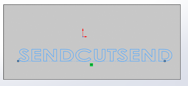
Once finished with editing the Text font, select the green checkmark under “Sketch Text”. At this point, the text placement can be modified. This can be done simply by clicking and dragging the centerline.
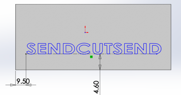
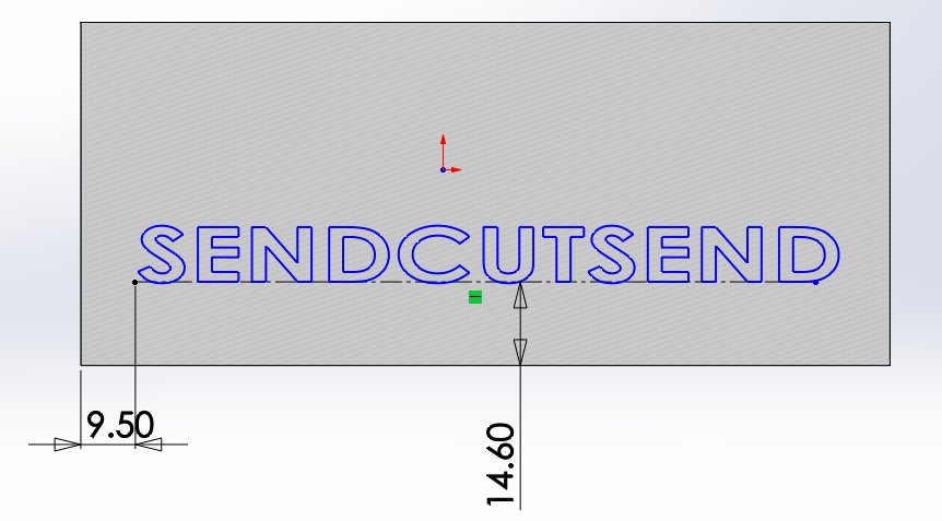
Another option is to prescribe dimensions between the centerline and outer edges of the flat plate. The dimensions in the figure below are in millimeters.
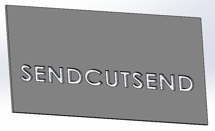
Extruding Text
Once the placement of the text is finalized, the text is ready to be extruded. Note that in SolidWorks, when text is created, the text is interpreted by SolidWorks as a sketch. Therefore, just like a regular sketch can be extruded, a text can also be extruded. The entire text is treated as a sketch. As a result, one can even use the extrude cut feature of SolidWorks and apply that to the text.
Apply the extrude cut feature to the text and treat the cut as “Through All”. Here’s how to create an extruded cut in SolidWorks.
Adding Bridges or Tabs
The final step is to create bridges or tabs inside some of the letters. Naturally, in 3D CAD space, there is no gravity, so it is not immediately obvious which parts of the laser cut designed letters fall out during the lasering.
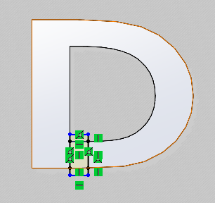
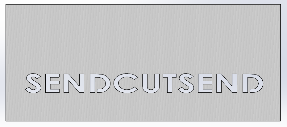
For example, the letter “D” in SENDCUTSEND requires a bridge to connect the inside material of the letter to the rest of the plate. This is easier to see in the pictures below.
To create a bridge, create another individual sketch in the desired location of the bridge, and extrude the sketch to the other side of the plate to complete the bridge. Upon doing this, the extruded feature becomes one material with the rest of the plate. As a result, the bridge maintains a connection between the internal material of the “D” and the rest of the plate material.
During laser cutting, the internal material of the “D” will stay connected. Make sure to review SendCutSend’s laser cutting design guidelines. Once the text is complete, sized and positioned correctly, and bridges have been created where necessary, you are ready to export to DXF.
Export and Save DXF File
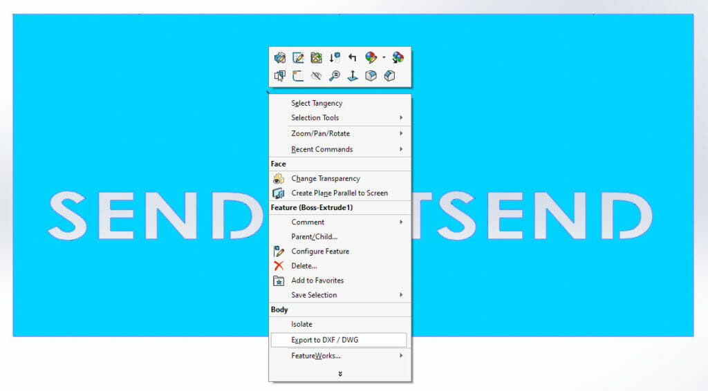
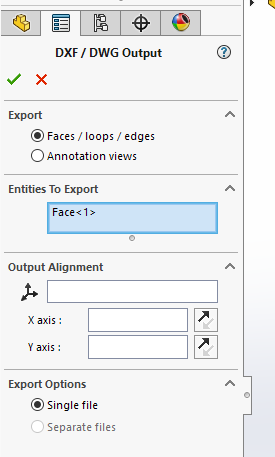
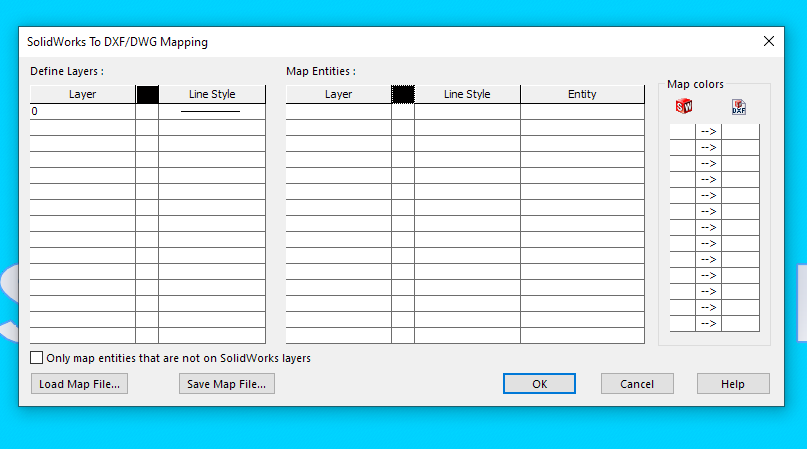
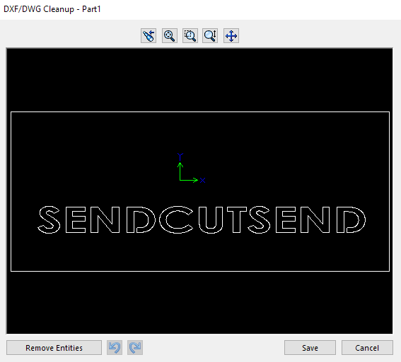
To export to DXF from SolidWorks, right click the face that you want to laser cut. Select “Export to DXF / DWG”. Select the folder in which you want to save the file. After that, a new pane will appear in the design tree called “DXF /DWG Output”. Select the green check mark. Next, a new mapping window will appear. Simply select “OK” since there are no bend lines necessary to map in this example design. Finally, a black window with the white-bordered representation of the design appears. Select “Save”.
Upload DXF File to SendCutSend Website
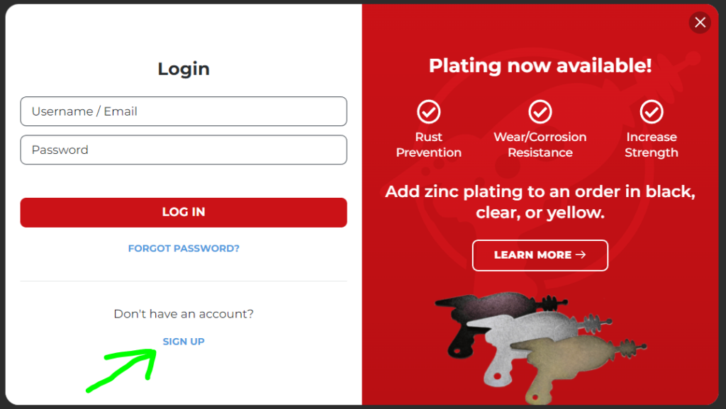
To upload the DXF file to SendCutSend’s website, log into your account first. If you don’t have an account, click on “Login” and “Sign Up” below where it says “Don’t have an account?”
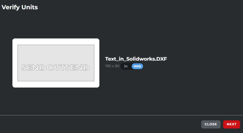
Once inside your online portal, click on “Add Drawing” toward the top right corner of the screen. Navigate to your DXF and upload the design. Verify the units that were used in the design before clicking on “Next”.

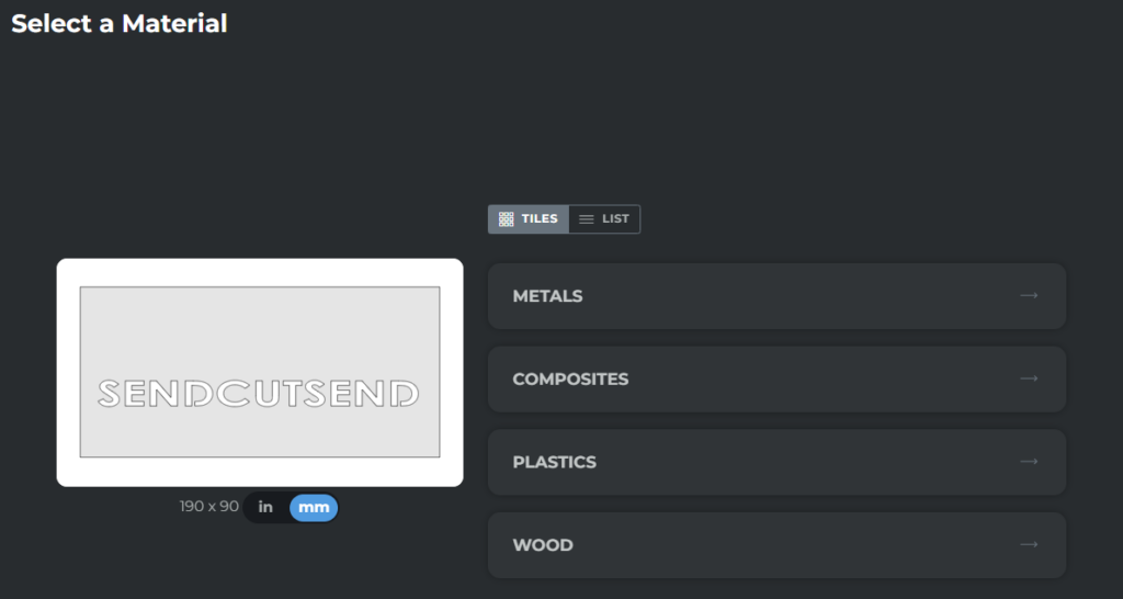
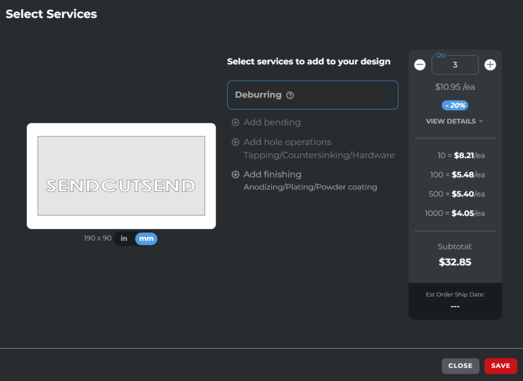
After the units are confirmed, SendCutSend gives you various material options. Select the material of choice and the material thickness desired as you navigate through the prompts. You will finally be prompted to specify quantity and select services to add to your design. SendCutSend offers a variety of services including bending, tapping, countersinking, hardware insertion, anodizing, plating, deburring, and powder coating.
To add services, click on the “plus” icon next to the service name. When finished with this step, click on “Save”.
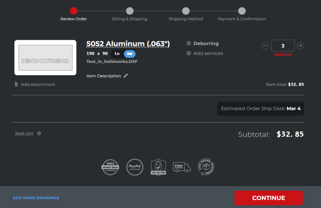
The next window that appears is the final subtotal quote window. Here, you can still change the quantity and view the change in price accordingly. Select “Continue” to move on to the shipping address and payment specification. Once everything looks good, confirm your order. Easy as that! Sit back and relax as SendCutSend brings your creation to life.
Visit the SendCutSend blog for addition SolidWorks and CAD tutorials. If you have questions or need assistance, feel free to reach out to our support team anytime.
Try our SolidWorks Plugin
If you are using SolidWorks 2021 or newer, check out our SolidWorks Plugin. You can upload to SendCutSend and get live quotes without ever leaving SolidWorks.
