At SendCutSend, we pride ourselves on fast, precise production that benefits businesses at any scale. However, our typical 2-4 day lead time for standard orders depends on cut-ready design files that meet our guidelines.
When you place an order with SendCutSend, your files are evaluated in a DFM (design for manufacturability) check. If all designs meet our guidelines, your order is released to production.
If any of your designs require changes before they can be produced, your order will be placed on hold and you will be contacted by SendCutSend’s support team with a request for revised design files. This can add a day or more to your order’s total lead time.
Once your files have been revised to meet our guidelines, your order will be updated and released to production.
Whether you need SendCutSend’s laser cutting service or other resources to create your products, understanding common file issues will save you time, money, and a few headaches! Here’s what to look out for.
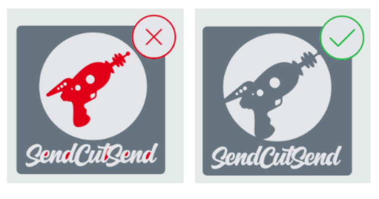
Pre-Nested Files
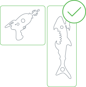
A “pre-nested” design file will have multiple parts saved within it, like this:
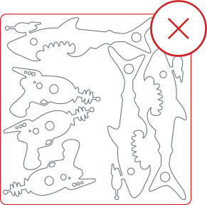
While all those sharks and laser guns look cool together, it’s unnatural for sharks to swim in schools. Lone sharks are better, especially when it comes to design files.
Designs that have multiple parts saved within them tend to slow down our production process. If pre-nested files that don’t meet our nesting guidelines are used to place your order, the order will be put on hold and SendCutSend’s support team will be in touch requesting updated files.
Additionally, pre-nested designs won’t benefit from our quantity discounts, which automatically apply to line items with quantities of 2 or more.
These files also misrepresent the true size of each part. This means that you may place an order that contains parts that are too small for us to cut in the selected material, or too small for us to process with services like linear deburring.
Nested Positive Signs
These are pre-nested files too, but you might not think of it that way since all the parts are components of the same design.
Typically the intent for these designs is for the separate letters to be cut so they can be individually mounted when they are received.
If you’d like to order a positive sign, that’s awesome! Just be sure to confirm that each individual letter meets our minimum geometry guidelines.
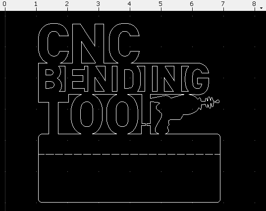
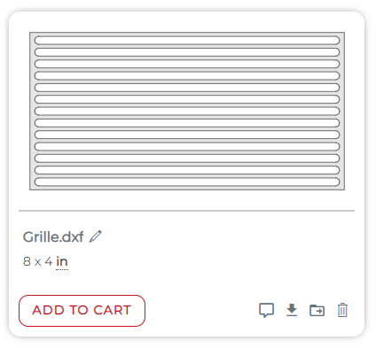
Loose Interior Shapes
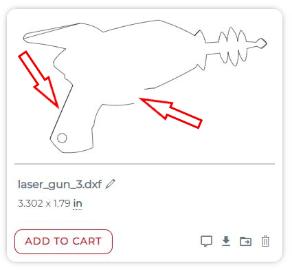
Designs must have all elements “bridged” so that no pieces will drop out and be lost during the production process. We’re unable to include dropped pieces with your order, so if you’d like all elements retained, they must either be bridged, or uploaded as separate line items.
For example, the red elements in this design will drop through and be lost because they are not connected to the rest of the part:

This can be fixed by adding “bridges” to connect the laser gun and interior text elements to the rest of the shape.

We have guidance on adding bridges to nested shapes here, and tips on preparing text for laser cutting services here.
When adding bridges, you may be using relatively small geometry. Be sure the bridges are at least the minimum bridge width needed for the material. You can find the minimum required bridge width by stock thickness on each individual material page.
Too Much Information
If uploading a 2D vector format file (DXF, DWG, EPS, or AI), your design should function like a simple map that the laser, CNC router, or waterjet can follow to cut your part.
Please do not send a design file that looks like this:
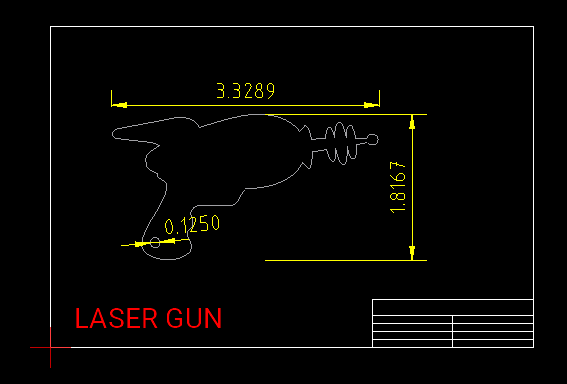
Ideally, we should only see the flat, 2D face of the part and cut paths at 1:1 scale, in either inch units or millimeters.
For cut parts with bending, we need just the cut paths and bend location lines at 1:1 scale.
Most design programs have export methods that enable you to save a file that will show the flat 2D pattern only. We have several guides available through our tutorials in our blog.
If exporting a vector file without a border or elements besides your flat pattern proves difficult in your design program, you can open your DXF or DWG in a 2D program like QCAD and manually delete any unnecessary paths.
We highly recommend QCAD since it’s a well-documented open source DXF editor. We have a detailed primer about preflighting your design using QCAD that’ll have you preflighting and fixing your files fast!
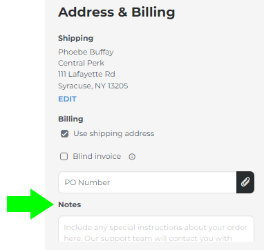
If you’re accustomed to sending technical or mechanical drawings with notes and other information to fabricators, we understand! It’s possible to add notes to your order before checking out. A member of the SendCutSend support team will contact you if there are any questions!
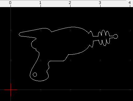
Perspective Drawings
It’s normally good to have some perspective, but not when ordering laser cut parts from SendCutSend.
Please try exporting the flat face of your part again if the drawing is previewing like the file named perspective below. Your drawing should preview like the file named flat.
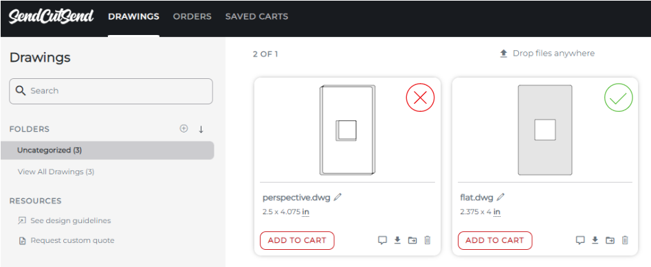
Perspective views can be the result from some design programs if the part is being viewed at an angle in the design workspace while the vector file is being exported. Make sure that only the flat, top-down view of your part is present when you export.
Bad File Exports
There are some red flags that tend to signal a poor file export or possible use of an online file converter.
These include
- Duplicate paths
- Intersecting paths
- Highly segmented paths with excessive nodes / anchor points
- Moderately segmented paths that should be smooth circles or arcs
Duplicate paths can be identified by both thickened lines and/or the absence of some lines in the preview of your file after it is uploaded to your account.
We have tips on how to identify and correct duplicate paths and other export issues in our QCAD guide, which is helpful for DXF and DWG files.
Often, another export attempt will solve the problem without the need to manually correct errors in the DXF or DWG. We have export tips for several popular design programs in our tutorial library.
If you’re working in Illustrator, we have an entire library dedicated to preparing successful Illustrator files for SendCutSend. We also have several Illustrator tutorials on our YouTube channel.
Generally speaking, we recommend exporting a clean file from your original design program if at all possible. Using online converters to force your design into the DXF, DWG, or Illustrator format can often result in the issues mentioned above.
STEP File Considerations
If you upload a STEP or STP format file, ensure your design meets our 3D File Guidelines.
Bent parts should be set up using SendCutSend’s bend radius and K factor specifications for the material thickness required. If the material thickness bend radius specification is not used in your design, you may receive an open entities error when you upload your file, or the part may not turn out as expected.
Geometry Too Small
Every material that SendCutSend cuts has critical minimum specifications for the smallest geometry that we can produce. These minimums have been established by testing and proving what we can cut well on a consistent basis.
While it may be tempting to request that we make an exception for your project, this will only delay your order’s progress into production and result in requests for revision, or suggestions that you switch to a different material we can cut the design in, if possible.
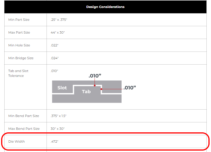
All of our critical minimums are available to view by stock thickness on each individual material information page at our Material Catalog.
Once you select your desired material and stock thickness, you’ll find the Min Hole Size, Min Bridge Size, and Min Hole to Edge Size under Design Considerations.
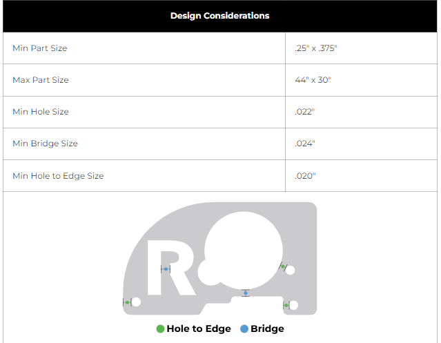
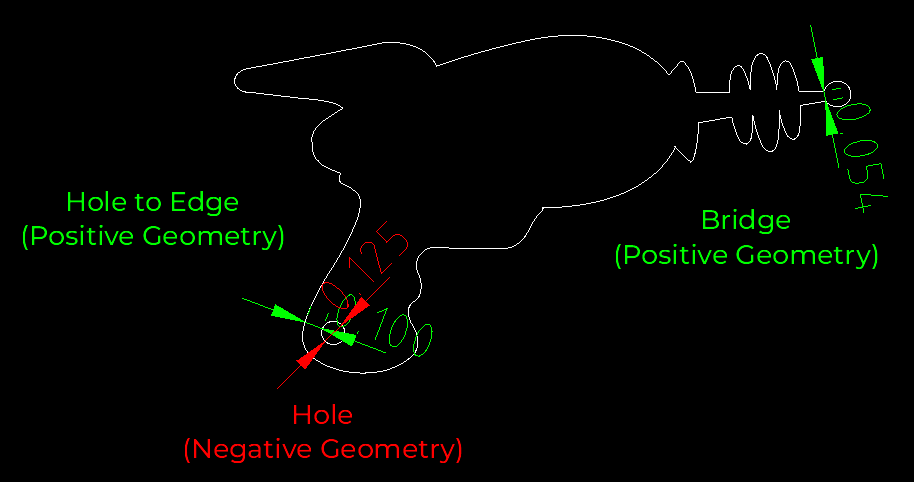
Min Hole Size: the minimum negative geometry we can cut in the material.
Min Bridge Size: the minimum positive geometry we can cut in the material.
Min Hole to Edge Size: the minimum positive geometry we can leave in the material between a cut edge and the edge of a circular hole that will have no operations applied such as tapping, countersinking, or hardware. Hole operations have separate minimums listed in the Material Considerations if you scroll further down.
The minimum distance required between two circular cut holes will also be the minimum hole to edge size value.
For some materials, the minimum hole size is more strictly defined by the cut method.
Because our CNC router uses a 0.125” drill bit to cut the geometry, the smallest hole we can cut in any CNC routed materials is 0.125”. We have more information about this on our CNC design guidelines page.
Our waterjet has a 0.070” cutting stream, so 0.070” is the smallest hole we can cut in most waterjet cut materials. We have more information about this on our waterjet design guidelines page.
If you’ll need tapping, countersinking, or hardware for any holes in your design, be sure to check out the guidelines pages for those services and review our hardware catalog. Each material info page lists specific minimum geometries for hole operations in the Material Considerations if you scroll further down.
We also have a guide that covers measuring minimum cut geometries in detail here: How To Measure Cut Geometry Specifications Using QCAD.
Design Density & Fragility
The amount of negative geometry in a design will affect how the part cuts depending on the chosen material and its cut method. Although we are able to cut fairly dense designs, we may need to put your order on hold and contact you if we have concerns.
Laser Cut Metal Parts
When we remove more than 50% of the material in an area, there is a tendency for the metal to “oil can” or distort from the stress relief while the part is being cut. This means pieces with a lot of material removed won’t be flat after we cut them, and will need additional finishing and flattening when they get to you.
Also, we cannot predict the amount of warping that may occur during the cut process due to the variability of internal stresses in rolled sheet metal. The laser cutting process itself releases and induces stress at the same time upon the material, so we cannot guarantee the relative flatness of parts after cutting. This is also highly dependent on the design geometry. This effect is present for all laser cut parts but becomes more pronounced the more material is removed. Check out our in-depth article about stress release and warping in laser cut parts.
For this reason, parts with 50% or more of the material removed are unlikely to be good candidates for our linear deburring process, which needs parts to be relatively flat to be deburred evenly. We have more information about this on our deburring page and in the video below.
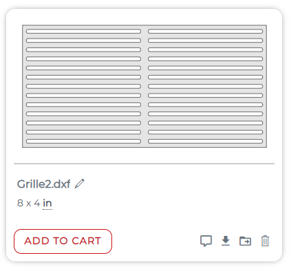
If a design looks like it could distort enough to be miscut or collide with the laser itself, we’ll recommend design changes to make the part sturdier. A design like this is a good example.
The long, thin negative geometry can result in significant warping, and the cut material in the slots could be a risk for jumping up and striking the laser.
For this design, we would recommend adding material back into the design and including at least one supporting bridge.
Although this revised design may still warp enough to prevent deburring, it would be less of a risk during the cut process.
CNC Routed & Waterjet Cut Parts
For CNC machined and waterjet cut parts, the 50% of material rule applies too, but for different reasons.
When designs are cut via these methods, a certain amount of vibration is induced during the cut process. While we have methods of minimizing this, if more than 50% of the material is removed, it becomes increasingly difficult for the part to remain still. To mitigate these factors, we generally recommend all positive geometry and bridging be at least 1:1 to the material thickness for a quality cut.
Shipping & Handling Considerations
If a design meets our minimum geometry requirements but looks like it will be susceptible to damage in shipping, we may put your order on hold and contact you to recommend revision. Birch plywood, MDF, and acrylic tend to be fragile. For more delicate materials, you may want to consider designing positive geometry to be at least 2x the material thickness in areas that aren’t being reinforced by the rest of the part.
Special Service Setup
If you leave an order note requesting etching or if your design has open interior paths, your order will be placed on hold so the support team can confirm how to proceed.
You can set your files up for single line etching or single line “no kerf” through-cuts in advance and leave a note per the instructions below to help your order move into production more smoothly. We have a detailed guide that covers considerations for these services and how to set your file up here: Setting Up Your Design for Single Line Etching or Single Line “No Kerf” Through-Cuts – SendCutSend
Bending Considerations
When it comes to sheet metal bending, there’s a lot to keep in mind while designing your parts. We have an in-depth guide about preflighting designs to be bent in QCAD here: Preflighting Bent Sheet Metal Parts in QCAD – SendCutSend
If you aren’t a QCAD (or other 2D program) user, the article may still be helpful as a comprehensive checklist for designs that require forming.
Bent parts should be set up using SendCutSend’s bend radius specification for the material thickness required. When designing a 2D flat pattern we strongly recommend using our Bending Calculator to ensure your parts turn out as expected!
If you upload a STEP or STP format file, ensure your design meets our 3D File Guidelines.
Here is a brief summary of the items that prevent orders from proceeding directly to production most often.
Cut Features Within Die Line
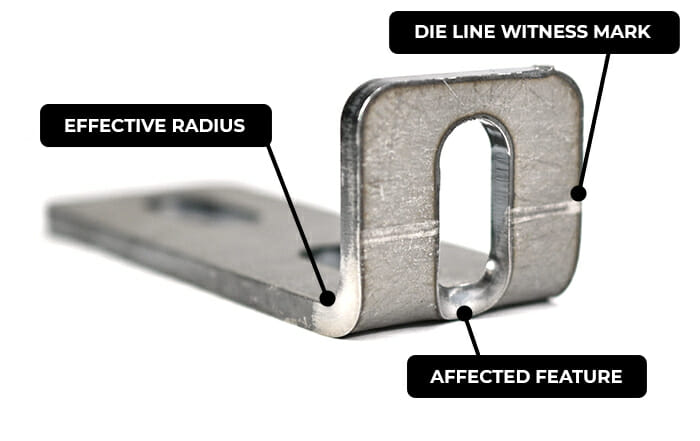
When cut features fall within the die line of our press brake’s tooling, they are likely to distort during the bend operation. We can bend parts that have cut features within the bend line, but we try to ensure you are aware that the features will warp.
For example, this design for a part in 0.063” 5052 aluminum has a cut feature highlighted in yellow that will be affected.
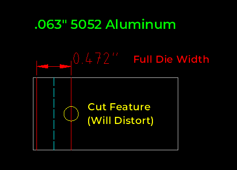
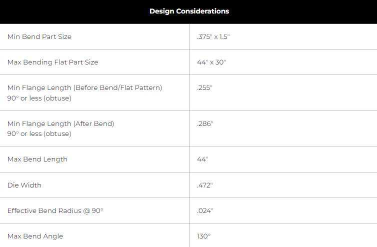
You can find the full Die Width for our bendable materials under Design Considerations on each individual info page at our Material Catalog.
Here is an example of what cut feature distortion and die line witness marks can look like:
Check out our guidance about this: Bending Deformation Guidelines
No Parallel Surface to Bend Line
In order to form parts accurately, each bend line needs a parallel surface for our tooling to gauge against.
If any of your parts lack a parallel surface to a bend line, we’ll place your order on hold and request a revised file. You can either update the design itself or add a tabbed surface that you can remove when the part gets to you.
We have detailed guidance on creating parallel surfaces here: Odd Flange Shapes

Check out our video about this:
Flanges Too Short
If your flanges aren’t long enough, there won’t be enough material for our tooling to “grab” and perform the bend operation. You can find both the Min Flange Length (Flat Pattern/Before Bend) and Min Flange Length (After Bend) for our bendable materials under Material Details on each individual info page at our Material Catalog.
Learn how to measure flange length.
U-Channel Too Narrow
Generally speaking, for u-channel bends in sheet metal, the base should be at least 2 times wider than the flange length.
For example, a 1.00” flange on two sides should have a minimum 2.00” base (base is the remaining material or the “bottom of the U”). The base can be greater than 2:1. For example, a 5.00” base with 1.00” flanges is acceptable (that would be a 5:1 ratio).

For polycarbonate parts, u-channels must abide by a 3:1 ratio.

See our channel bend writeup for detailed guidance.
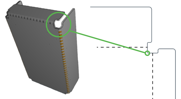
Insufficient Bend Relief
Bend relief essentially refers to having enough space for the bend to occur without distorting or tearing the material. We have a complete guide to designing bend reliefs.
You can create relief by adding notches to your design, or by moving the bend location itself.
The total recommended bend relief depth (or bend relief space) should equal to Material thickness + effective bend radius +.020”. You can find the Recommended Relief Depth by stock thickness on each material info page.
The total relief depth is measured from the bend line to the bottom of the relief. The bend location line should mark the center of the bend.
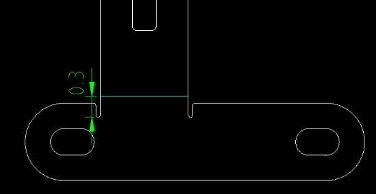
If a part does not not have sufficient space for the bend operation, you can add a notch, circle, or rectangular relief. These notches allow for less stress on the inner radii of the flanges, and will help keep the corners of the bends from interfering with the base material.
Please note, polycarbonate parts must have rectangular reliefs, and they must meet the minimum relief depth required to avoid cracking.
Making It Work
Congratulations! You now know the most common design sticking points and have a cheat sheet for surviving the DFM gauntlet! When you’re ready to make use of SendCutSend’s laser cutting service again, your production run is sure to pass with flying colors.
Check out our FAQ page for helpful info, and stay tuned to our blog and YouTube channel! You can also reach out to our support team anytime for answers and assistance.


