When reviewing your design to confirm it meets our guidelines, the first item to check is your part’s overall size and cut feature dimensions versus SendCutSend’s critical geometry specifications for cutting in the material you need and given the operations required for your part.
SendCutSend’s minimum hole, bridge, and hole to edge size values have been proven out by rigorous testing, and represent the smallest features we can cut cleanly and reliably for any size production run. Our applications team will reject designs that do not meet these specifications and request revision, adding to your order’s lead time.
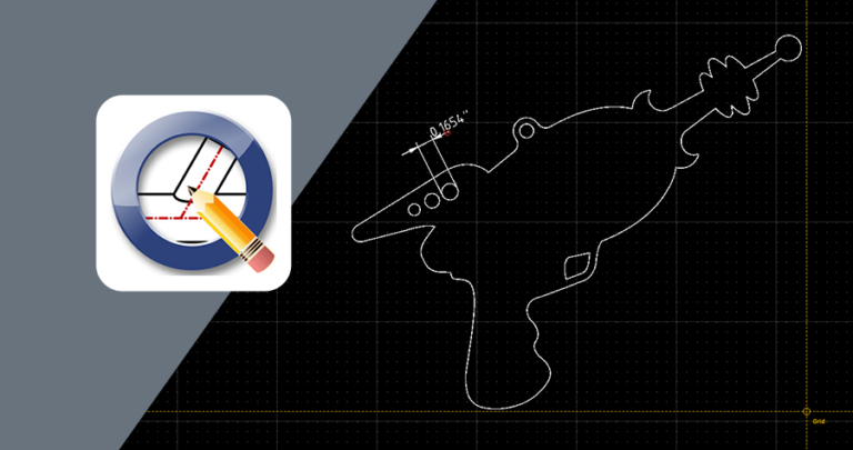
Not to worry, though! We have tips in this guide for measuring your 2D file in QCAD, a free program you can download and set up with the help of our guide here.
Using the Material Pages
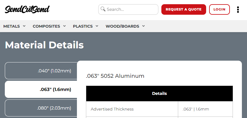
Once you’re set up with QCAD, it’s time to find your “material cheat sheet.” Each material info page located in our materials directory includes all specifications for every process by stock thickness.
Design Considerations
Once you’ve navigated to the specific material page, just scroll down to Material Details and choose the desired stock thickness on the left.
New Image
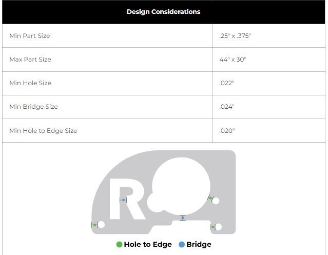
Then, scroll down to find the Design Considerations. There you’ll find the minimum and maximum overall part sizes we can cut in the material depending on the operations needed, and the minimum hole, bridge, and hole to edge sizes we can execute for cut features.
Min Hole
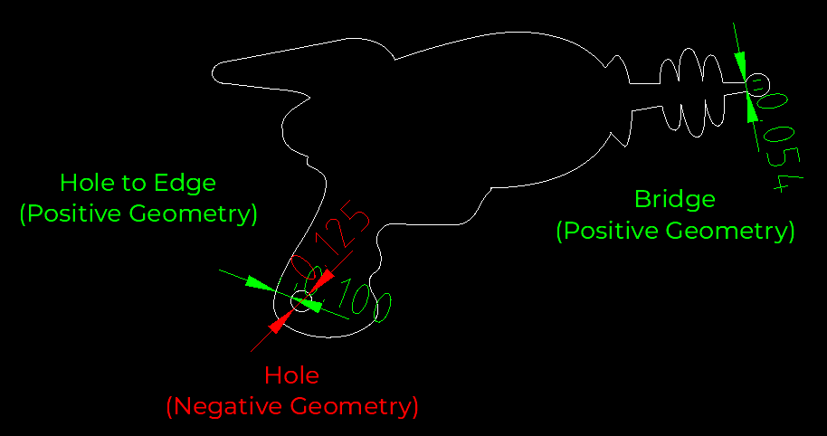
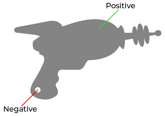
Min Hole Size: the minimum negative geometry we can cut out of the material without risk of misshapen features, melting, or damage to our equipment.
Negative geometry can include holes, slots, and notches. It’s what is ‘negated’ from the parent material.
Min Bridge vs. Min Hole to Edge
Min Bridge Size: the minimum positive geometry we can leave in the material between two non-circular cut edges without risk of burn-off, burn-through, or damage to our equipment.
You can also think of ‘bridges’ as webbing, wall thicknesses, or external features protruding from the main body of the part. It’s what remains of the parent material and creates the part itself.
Min Hole to Edge Size: the minimum positive geometry we can leave in the material between a cut edge and the edge of a circular hole that will have no operations applied such as tapping, countersinking, or hardware. Hole operations have separate minimums listed in the Material Considerations if you scroll further down.
The minimum distance required between two circular cut holes will also be the minimum hole to edge size value.
Hole Operation Considerations
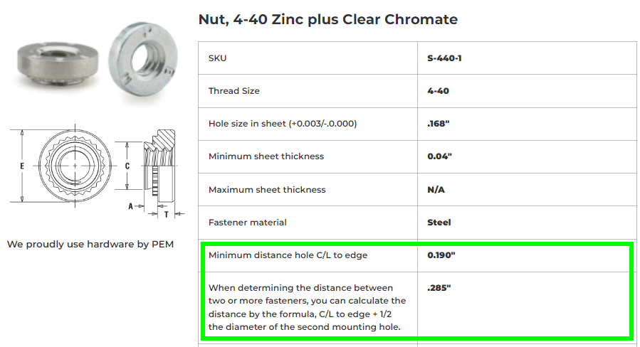
If you’ll need tapping, countersinking, or hardware for any holes in your design, be sure to check out the guidelines pages for those services and review our hardware catalog.
In the hardware catalog, each hardware size has a minimum center of hole to edge of nearest cut feature value listed, as well as instructions for calculating the needed distance between adjacent hardware holes.
Using QCAD
Preferences
Before starting to measure, you might want to review your drawing and application preferences.
We have tips on how to do this here.
With your preferences set up, you’ll ensure that
- Dimensions are displaying properly
- The cursor will automatically snap to points as desired when measuring
- Mouse behavior is dialed in
- Drawing units are correct
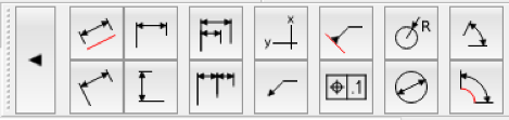
Dimension Tools
QCAD has an array of dimension tools, but there are a few you’ll use repeatedly to measure features:
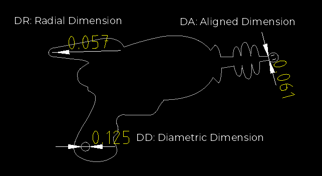
- Aligned Dimension – measure between two points (keyboard shortcut DA)
- Diametric Dimension – only measures true circles (keyboard shortcut DD)
- Radial Dimension – only measures true arcs (keyboard shortcut DR)
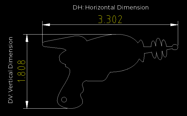
For measuring overall part size, these convenient tools measure dimensions at a fixed angle:
- Horizontal Dimension – angle fixed at 0° (keyboard shortcut DH)
- Vertical Dimension – angle fixed at 90° (keyboard shortcut DV)
You can view all the Dimension tools by pressing the keyboard shortcut WD.
Demarcation Tools
There are tools that aren’t intended for measuring, but come in handy for marking distances:
- Modify > Offset with Distance (keyboard shortcut OF)
- Draw > Circle > Center, Diameter (keyboard shortcut CA)
Offset with Distance
Offset with Distance will create parallel polylines to existing paths that are offset the distance you enter into the Distance field.
If you have QCAD Professional installed, you can also choose between Whole or Segment Polyline Mode. For Whole Polyline mode, there is a round or miter join option. Toggling clipping will clip most intersecting polylines in Whole Polyline Mode.
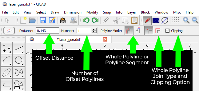
For our purposes, a single offset polyline is all we need to mark distances, so QCAD’s free community edition will work just fine!
Although Offset with Distance is a Modification tool, it can help visualize design considerations like die line distortion. You can learn how to mark SendCutSend’s die widths on your bent parts using the Offset with Distance tool here.
You can also use the tool to quickly scan over your design and see if geometry is below SendCutSend’s minimum specification for the material.
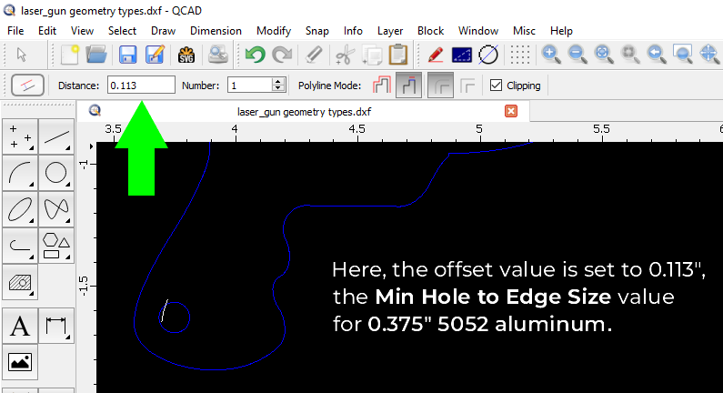
For example, if we wanted to cut this laser gun in 0.375” 5052 aluminum, we would need to make sure all bridging is at least 0.143” wide and the distance between the edge of the circular hole cutout and any other cut edge is at least 0.113” wide.
We can input the value 0.143” into the Offset with Distance tool to offset 1 polyline segment.
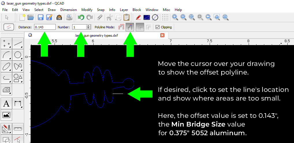
Then, we can move the cursor over the part to show where the polyline is intersecting with cut paths and revealing areas that are too small.
To mark a distance, you can click to set the polyline in a desired location.
Below, the offset value is now set to the minimum hole to edge size for the material.
If minimum design change is desired, switch to a material / stock thickness that can tolerate the current geometries.
If the 0.375” 5052 aluminum is a must, then widen all geometry to the minimum specifications.

Draw a Circle
Another way to check feature minimums is by drawing a circle with a diameter of the minimum hole, bridge, or hole to edge value, and moving the circle around your design to see if areas are too small.
You can view all Circle Tools by pressing the keyboard shortcut WC.
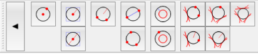
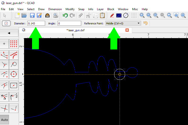
The diameter-based circle tool (keyboard shortcut CA) will allow you to input a value for the circle’s diameter. It defaults to using a center reference point to place the circle, but you can easily change that at the drop-down menu.
Auto Snap
If Auto Snap is toggled on, the circle will try to ‘snap’ to any points that have Auto Snap turned on in the Application Preferences.
You can update your Auto Snap settings by pressing Ctrl +, or navigating to Edit > Application Preferences.
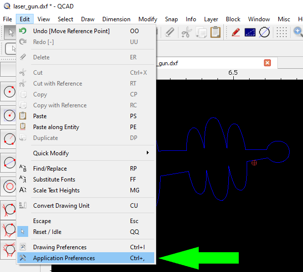
Once Application Preferences is open, search for snap to quickly access the Auto Snap settings.
Then, update the settings to your preference.
If you want to be able to smoothly move the circle over your design without it snapping onto points, you can turn Auto Snap on and off.

- Keyboard shortcut SF: Snap Free – Freely position your cursor; Auto Snap is turned off.
- Keyboard shortcut SA: Snap Auto – Auto Snap is turned on and will reference the settings in Application Preferences.
You can toggle Auto Snap on and off in a few ways:
- Press quick keys SF or SA
- Click the + or Auto tiles to switch between free positioning and Auto Snap
- Navigate to the Snap menu to turn Auto Snap on or off.


Radial Considerations
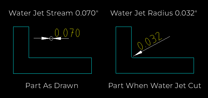
For materials cut via CNC router or water jet, the cutting path itself is a more significant design consideration than with laser cut materials.
This is because of the wider toolpath’s radius, which limits the amount of definition possible.
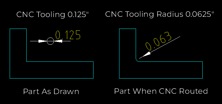
Our CNC router cuts material with a 0.125” bit. All interior corners will have a 0.0625” radius.
Our water jet has a 0.070” cutting stream, so interior corners will have a 0.032” radius.
Previewing Detail Loss
There are a few ways to check and see how parts will look after they are cut.
Draw a Circle
You can Draw a Circle, set the diameter to the tooling’s width, and move it around your design to see if any features will lose definition when the part is cut.
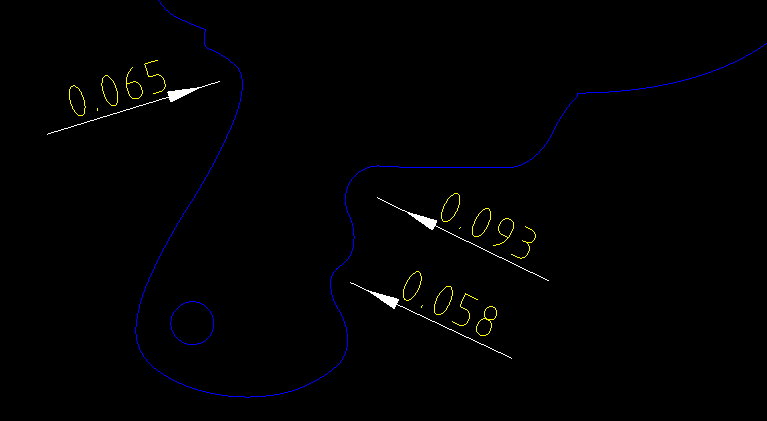
Measure Radii
You can also use the Radial Dimension tool (keyboard shortcut DR) to measure arcs and see if they will lose definition. Any arc less than the tooling’s radius value will be blunted.
Draw Arcs
Another option is to use the 2 Points and Radius arc drawing tool (keyboard shortcut AD) to draw arcs illustrating the tooling’s radius.

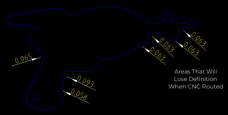
In this image, you can see that the finer details on the laser gun will be lost if cut via CNC router, due to the CNC tooling’s inherent radius.
Measure Twice, Cut Once!
With QCAD’s handy features in your toolkit, you’re ready to get started with an A+ production run or prototype. Make sure your design meets all guidelines and check out our other tutorials for more tips on creating successful parts.
Once your drawing is free of common problems and passes the setup checklist, upload your file to SendCutSend’s instant pricing tool and we’ll bring your ideas to life!
