Welcome to the third installment of our three-part series on how to design your own custom laser cut parts. In this guide, we’ll show that anyone can create unique items using free 2D illustration software. Make sure you have Inkscape installed to get the most out of this tutorial!
Inkscape is an excellent free software for aesthetic items. We don’t recommend this program if your project needs a high level of precision (for example, you need bending, tapping, countersinking, or hardware services.) CAD programs like Fusion and QCAD are ideal for any mechanical parts.
Check out our full list of recommended software here: Recommended Software for Laser Cutting
Other guides in this series:
Forget the Hardware Store – Design Custom Laser Cut Parts Instead
Forget the Hardware Store – Design Custom Bent Sheet Metal Parts Instead
Designing Decor
When you need to create something decorative, a 2D illustration program like Inkscape can be the best choice. The interface may feel more intuitive for these projects compared to traditional CAD software, and illustration programs export better files for designs with irregular curves.
First: Choose Material and Services
Before diving into Inkscape, first, we’ll need to confirm our material choice and if we’ll add any services.
In the previous two guides, we’ve used 0.059” G90 galvanized steel to create strong, corrosion-resistant parts. G90 works for decorative objects too if you (or a gift recipient) enjoy an industrial aesthetic.
If you’d prefer something a little flashier, SendCutSend has plenty of options! Brass, copper, and stainless steel are naturally good-looking materials that clean up nicely with our deburring service. For aluminum and mild steel, we offer anodizing, plating, and powder coating services that add protection and pizzazz.
Please note: when adding any service, check out the What To Expect section on the specific guidelines page for outcome examples and information.
For this part, we’ll create a text-based design in 0.048” mild steel with the intention to add powder coating.
Then, Confirm Design Considerations
To see all design considerations for any material, navigate to SendCutSend’s Materials Library and locate the material. Then click to visit the material page, and scroll down to find the Material Details and Design Considerations.
Under the Material Details, you can see that 0.048” mild steel is a laser cut material, so be sure to review SendCutSend’s laser cutting design guidelines. Depending on the material you choose for your project, you may need to review the CNC routing or waterjet cutting guidelines instead.
0.048” mild steel has the following critical minimums for cutting, per the Material Details:
- minimum hole size for cutting is 0.018”
- minimum bridge size is 0.024”
- minimum hole-to-edge size is 0.020”
- minimum overall part size is 0.250” x 0.375”
Powder coating has a few critical design considerations for the service:
- minimum overall part size for powder coating sheet metal is 1.00” x 3.00”
- designs must include at least one hole that is at least 0.063” wide, or at least the minimum hole size for cutting in the material, whichever is larger
- this is required for processing
- no holes may be smaller than 0.040”
- this prevents powder from clogging
Since we are adding powder coating, the minimums for that service override the minimums for the material where applicable.
With the guidelines confirmed, we can start making a gift or any decorative object!
Inkscape Process
1. Workspace Setup
After starting a new document in Inkscape, navigate to File > Save As to save the document. This will make it easy to continuously save your work as you go. Inkscape’s default file format is SVG and that is ok while we’re working on the design. Later, we’ll need to save the design as an EPS file when it is finished.
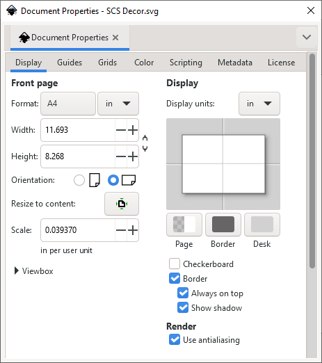
Once your document is saved, set the measurement units and page/background size to your preference by adjusting the Document Properties. You can access this by navigating from the toolbar to File > Document Properties or pressing Shift+Ctrl+D.
Your front page/background/artboard should be at least slightly larger than the design you intend to create, and the units should be either inches or millimeters.
When you make changes here the document will update automatically.
For this design, we’ll use inch units.
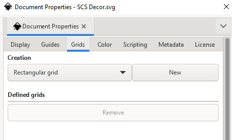
If you like, you can also create a grid for the document under the Grids tab.
Click New to create a grid.
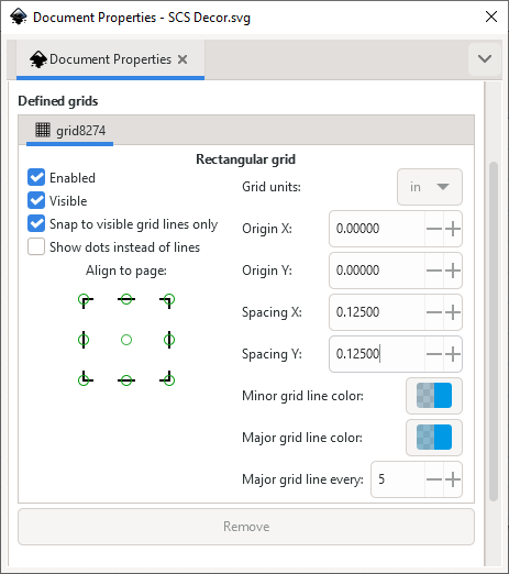
Then, set the Grid units to be consistent with the document units and update the Spacing X and Y as needed.
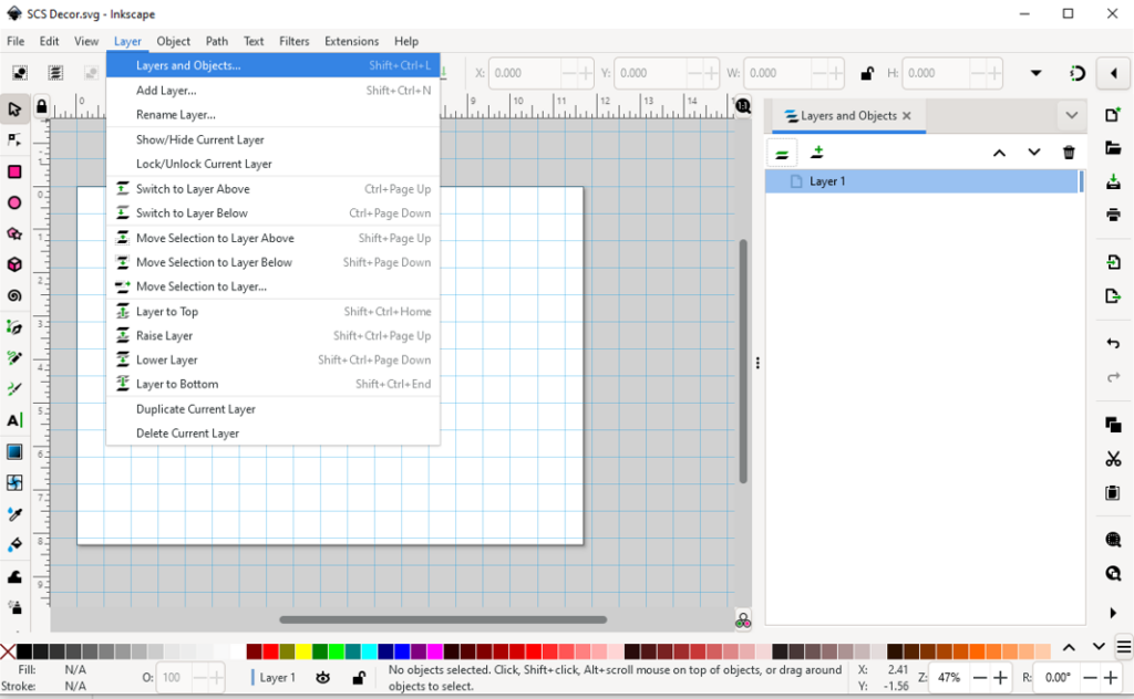
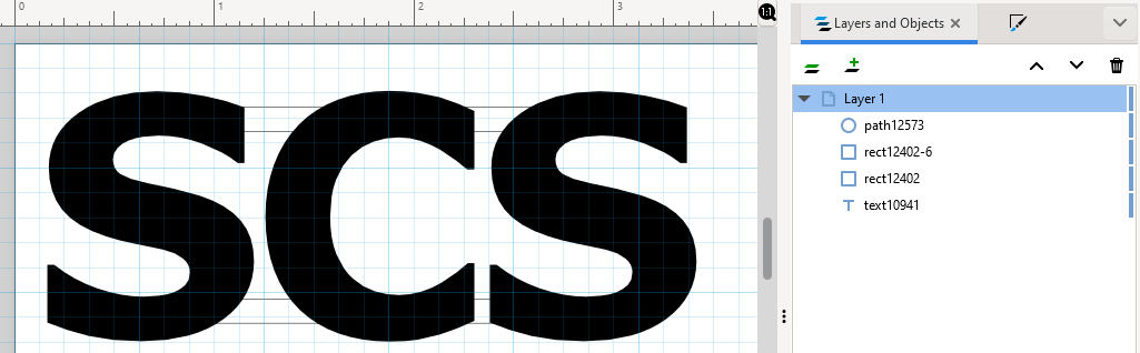
Next, make the Layers and Objects list visible by either navigating to Layer > Layers and Objects or pressing Shift+Ctrl+L. This makes it easy to see all the components of your design, whether they’re an object or a path, and whether they are grouped.
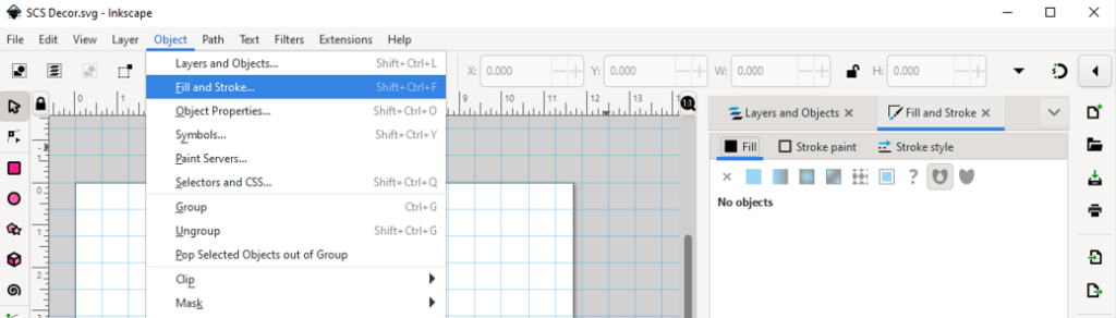
Then, navigate to Object > Fill and Stroke or press Shift+Ctrl+F to add the Fill and Stroke settings to the right panel. This makes it easy to add, remove, and change fills and strokes.
2. Start Designing!
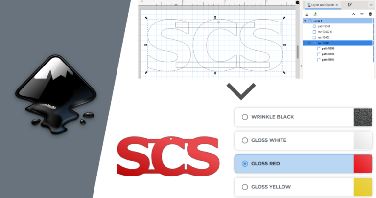
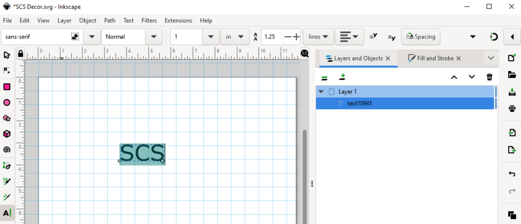
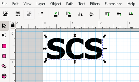
You can use the shape and text tools in Inkscape to come up with pretty much anything. Here, we’ll type SCS using the Text tool (keyboard shortcut T) and connect the letters using some rectangular shapes.
The Text tool allows you to change the font, size, unit of measurement, spacing, and orientation like most other design programs.
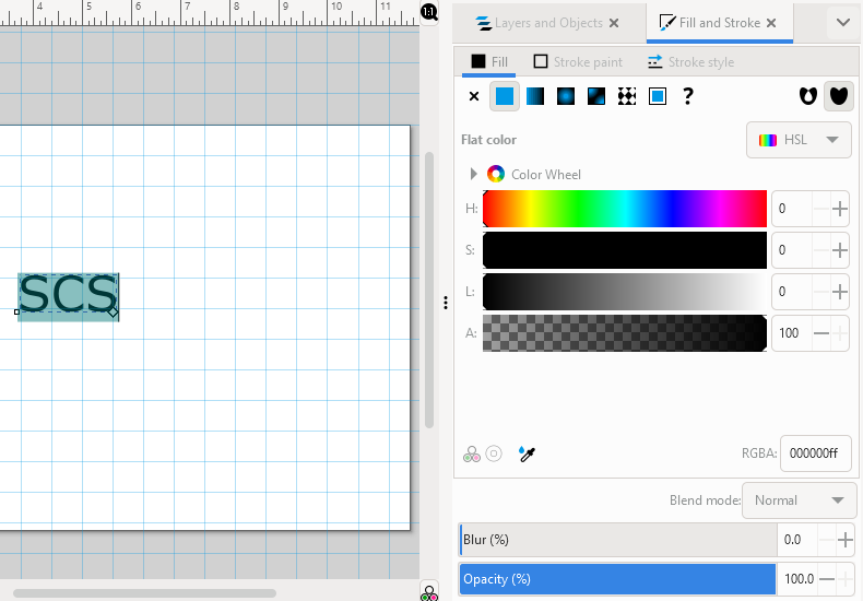
At our Fill and Stroke tab, we can see the text has a solid black fill and no stroke. This is ideal – all objects/paths should have a solid fill at 100% opacity, or a stroke at 100% opacity, but never both.
Solid fills are typically the best way to preview what your actual part will look like, so we recommend using only a fill whenever possible.
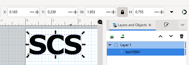
After adjusting the text style we want to scale the text overall. You can either do this in the text tool or by using the Select and transform objects tool (keyboard shortcut S).
To lock the proportions of an object while you scale manually by clicking and dragging an arrow, hold the Control key.
You can also click the lock icon between the width and height information fields when the object is selected to permanently lock the proportions.
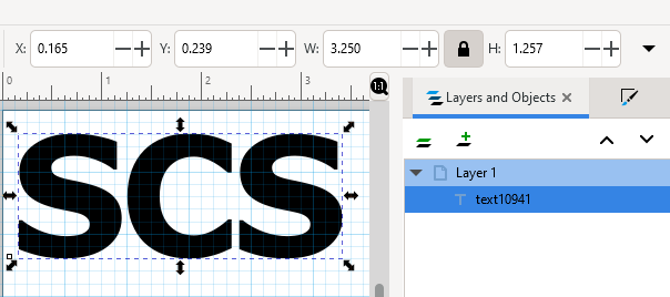
For this design, we’ll scale it up to a little over 3.00” long to meet the minimum overall size requirement for powder coating services.
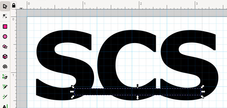
Now we’ll draw a rectangle to connect the letters using the Create rectangles and squares tool (keyboard shortcut R).
You can type in the exact dimensions you want or create the shape manually using your cursor.
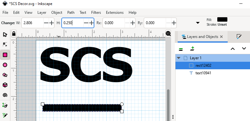
After the shape is drawn, you can always adjust its size and position later using the Selection tool.
Once a shape is set the way you like it, you can copy and paste it if needed.
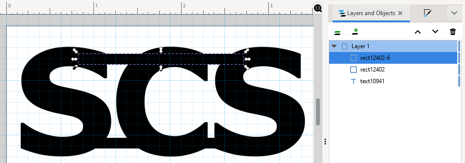
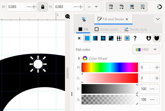
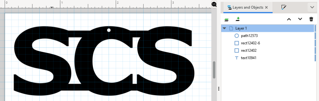
Since this part will be powder coated and may also be hung in an ornamental fashion, we’ll add a 0.063” hole as well, with a solid white fill.
The design looks just about ready!
3. Check Design Paths
Some drawing tools will draw path-based shapes, while others create objects that need to be converted to paths.
Along with checking the Layers and Objects list, you can also view designs in Outline mode which will show the actual paths present in your design. Before saving your finished design as an EPS file, ensure it looks right in Outline mode. The paths represent the actual paths the laser will take to cut your part.
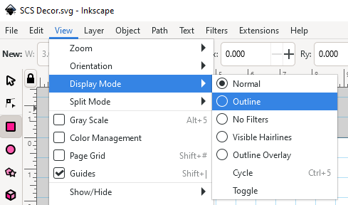
When viewed in Outline mode, the text isn’t outlining which means it needs to be converted to paths.
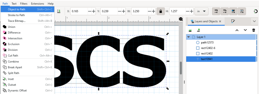
To convert any object to a path-based shape, select the object. Then either navigate to Path > Object to Path or press Shift+Ctrl+C.
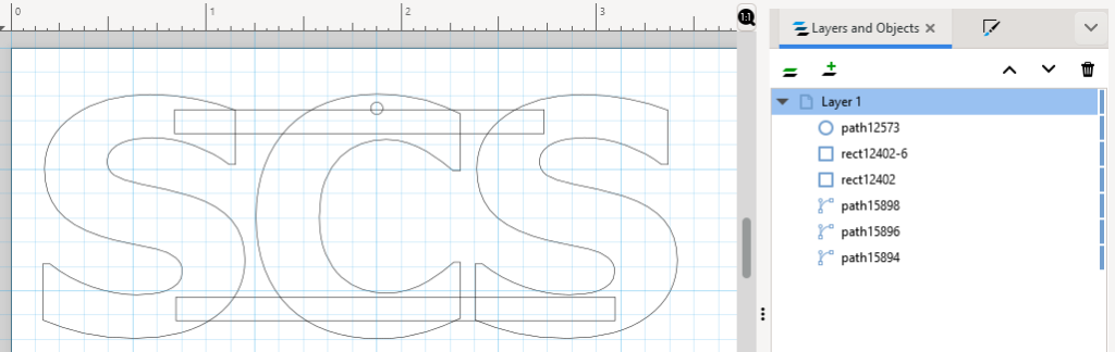
Then, you’ll see all the paths in Outline mode!
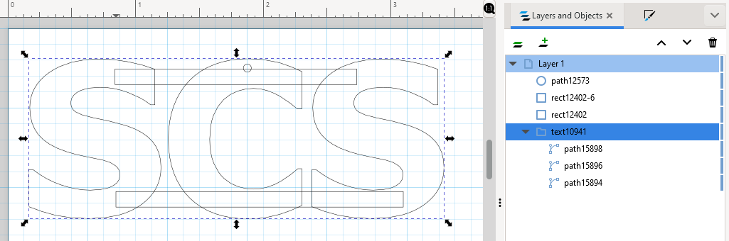
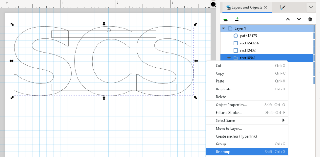
Each letter is now a path under a text group in the right panel. We don’t need anything grouped, so we’ll right-click on the text group and click Ungroup. You can also click the group layer and press Shift+Ctrl+G.
Now our layer list looks good but we have some intersecting paths to resolve.
We can’t accept files with intersecting paths because the laser needs a clean, closed path to follow to cut each shape.
4. Merge Shapes If Needed
First, we’ll hide the circular hole path by clicking the eye icon by the layer.
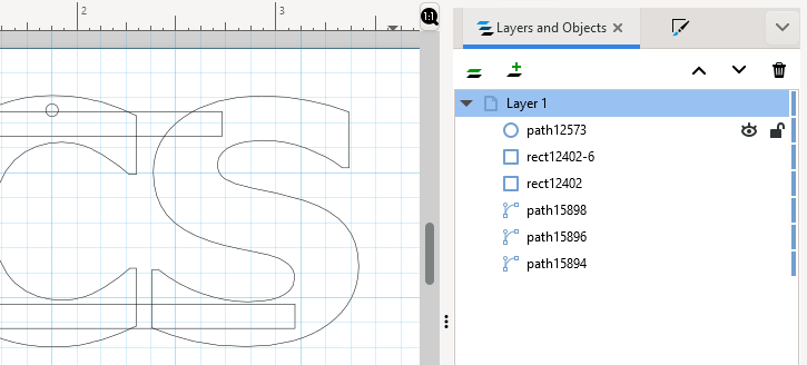
This is because we want to merge all the other shapes first.
Once the circle is hidden, select all the other layers and navigate to Path > Union or press Ctrl+ +.
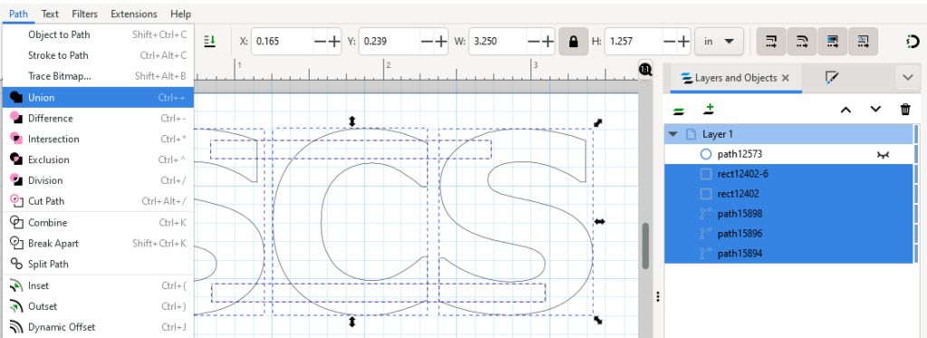
This will unite all the paths into a single shape!
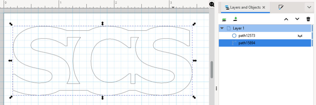
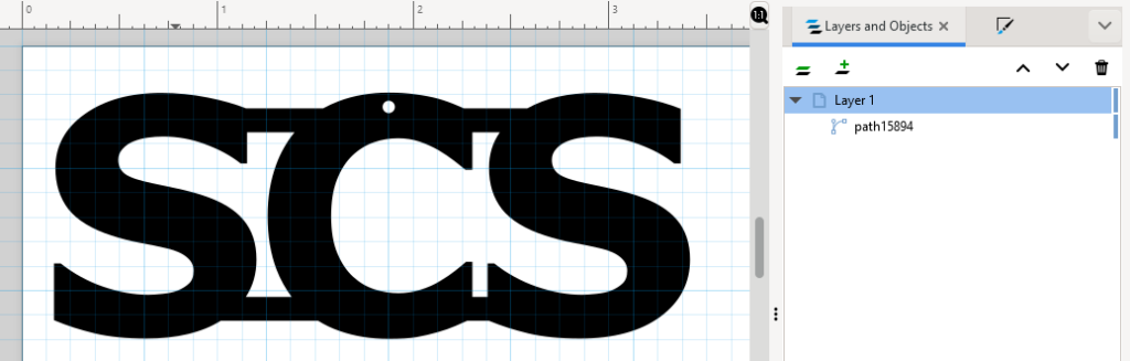
Now, you can click the eye icon to make the circle visible again.
Then, select all layers and navigate to Path > Exclusion or press Ctrl+ ^.
This will merge the paths so the hole cutout is retained. When the design is viewed in Normal mode, the solid fill shows that the single shape reflects the intended design.
5. Simplify Paths If Needed
The last touch will be simplifying paths.
All paths have nodes or anchor points that show the beginning, middle and end of the path, and the number of nodes may depend on the type of path. Each node/anchor point will ultimately represent a stopping point for the laser while it is cutting your design. Therefore the minimum possible number of nodes is ideal for optimal cut edge quality.
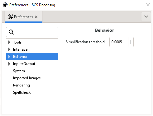
Before using Inkscape’s Simplify tool, adjust the settings for the tool to prevent it from simplifying paths too aggressively. If paths are oversimplified, they will have a warped or melted appearance.
To adjust the settings, from the toolbar navigate to Edit > Preferences. Then click Behavior to access the Simplification threshold setting. It’s strongly recommended that you set it very low, around 0.0005, and only increase the threshold if necessary.
Once that is done, select the design and switch to the Edit paths by nodes tool (keyboard shortcut N). This allows us to see the original quantity of nodes and observe how many are removed by simplifying.
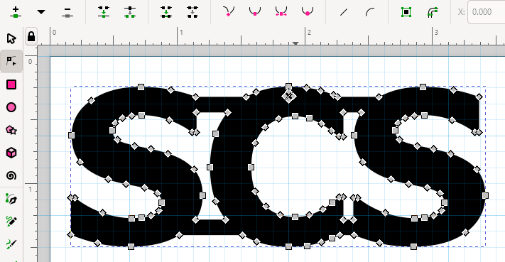
Now, either navigate to Path > Simplify or press Ctrl + L. The Simplify tool will immediately take effect.
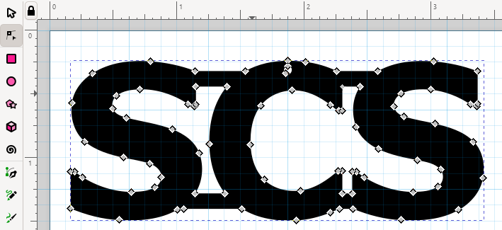
It’s a good idea to zoom in closely and see if any small features have been warped. Here we can see that the circle and letter tips are slightly deformed.
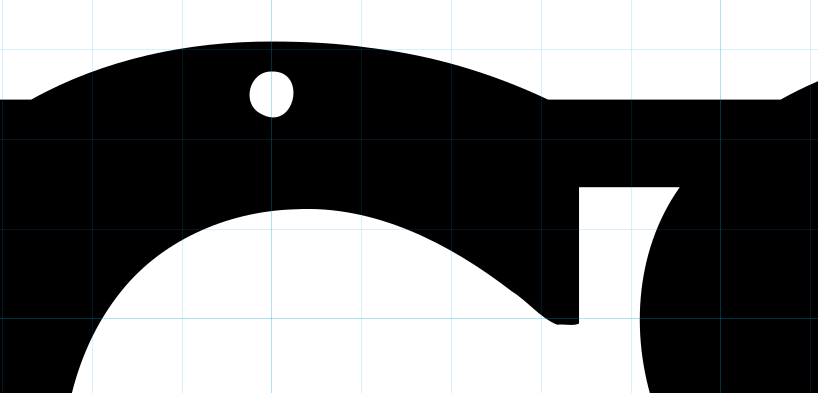
Due to the warping, we’ll undo that simplification and lower the threshold.
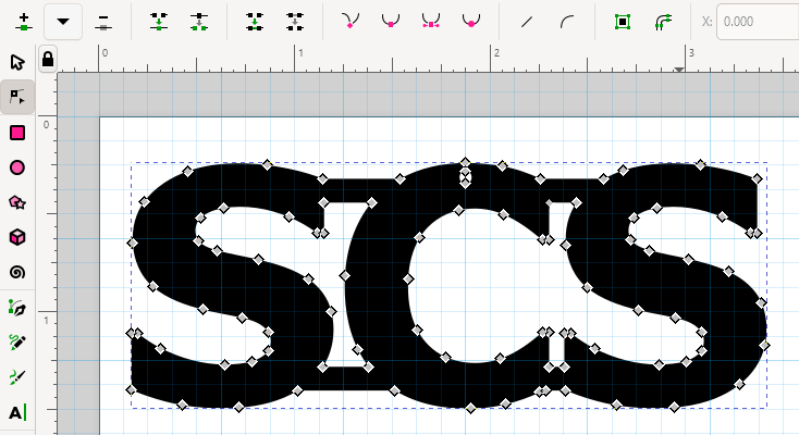
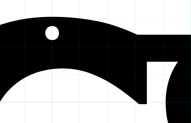
With a threshold of 0.0003, we achieve almost the same benefit without deformation.
6. Double Check Dimensions
Review the design to ensure all geometry meets the requirements for the material and any intended services.
We already know the overall part size and minimum hole size specifications are met, so we just need to check that no bridging is too small. The grid currently shows that we should be OK on that front, but we’ll go over a tip for more specific measurements.
The quickest and easiest way to check dimensions in Inkscape is by drawing a temporary circle with a diameter that matches the minimum dimension you want to check against. Give the circle a brightly colored fill and move it around the design to check if everything meets the minimum.
For this design we’ll set the diameter to 0.024” to match the minimum bridge size for 0.048” mild steel.
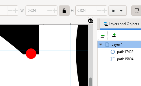
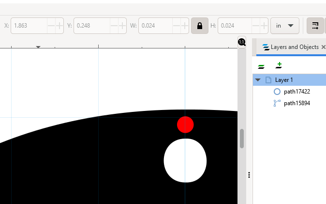
Looks like we’re good to go! Delete the measuring circle and get ready to save.
7. Save File As EPS
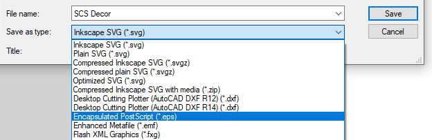
When the design passes SendCutSend’s file setup checklist, it’s time to save the file in the EPS format.
Just navigate to File > Save As, then access the dropdown menu for Save as type and choose Encapsulated Post Script (*.eps).
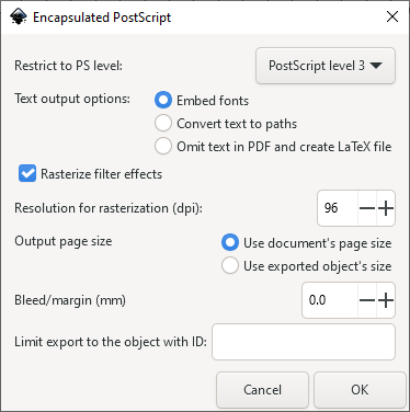
After this you’ll be asked to confirm the EPS settings. You can leave them as-is and click OK.
Please note: Inkscape can save files in the EPS format, but the program cannot open and edit them. If you decide to make further changes to your design after saving it as an EPS file, be sure to re-save it as an SVG or reopen the original SVG file.
8. Upload to SCS Website
You should be able to upload your EPS file to SendCutSend’s website, preview the design, and confirm that the correct overall size is showing.
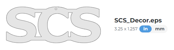
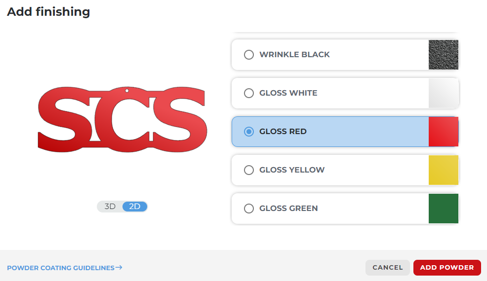
Then select your material and any additional services!
If your design doesn’t look the way you expected in the part preview, check out Designing for Laser Cutting in Inkscape and our other Inkscape guides for tips on preparing and exporting your design for laser cutting.
Conclusion
Coasters, fire pits, and signs, oh my! Hundreds of SendCutSend customers have designed objects they love living with (take a look at these featured examples.) Join their ranks by designing a custom laser cut gift or totally unique piece of decor that can’t be found anywhere else. And who knows – you might end up with some customers of your own. Happy designing!
Want to know what happens after you place an order? Learn about SendCutSend’s processing times and shipping speeds.
Other guides in this series:
Forget the Hardware Store – Design Custom Laser Cut Parts Instead
Forget the Hardware Store – Design Custom Bent Sheet Metal Parts Instead
