

| Adobe Illustrator | .ai |
| AutoCAD | .dxf, .step, .stp |
| CorelDraw | .eps |
| Fusion360 | .dxf, .step, .stp |
| Inkscape | .eps |
| SolidWorks | .dxf, .step, .stp |
For laser cutting, we accept 2D vector files in the following formats: DXF (Preferred), AI (Adobe Illustrator), EPS, and DWG.
We also accept 3D files in the STEP and STP formats. If there’s trouble uploading your file, please see our STEP/STP file guide.
If you design your parts in non-CAD software (Adobe Illustrator, Inkscape, CorelDraw) please send us the original (native) .ai or .eps file. We’ll take care of the conversion on our end.
Please note that we cannot accept or process STL (mesh) files or raster-type (JPEG, TIFF, PNG, BMP) files.
We have tutorials to help you convert your art to a vector format in Adobe Illustrator and Inkscape.
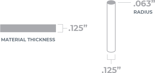
For composite materials, we use a CNC, chip-subtractive method (2-dimensional CNC flatbed machining) to cut your parts. We’ll use a 0.125″ bit, so allow for a radius of .063” on all internal geometry and minimum hole size of .125”.

For composite materials, we are limiting the minimum and maximum part sizes in order to provide you with the quickest and most efficient CNC machining possible.
Overall size limitations for cutting by material can also be found in our part sizing chart.
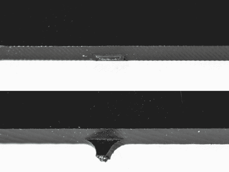
All parts machined using the CNC router will have small fixturing tabs leftover on the edges. We use these tabs to ensure your parts remain in place and secure during the manufacturing process.
Tabs will be approximately .1875″ wide, and the depth will be equal to half of your chosen material thickness. These tabs can be easily sanded down and will not affect your final design in any way.
Check out our information on using fixture tabs in CNC machining if you have further questions.
Inside angles (acute angles) will have a slight radius due to the use of a round cutting tool. The radius will be .063″ due to the tool’s .125″ diameter.
Outside corners are unaffected, but tooling limitations make it impractical for us to produce perfectly square or sharp inside corners.

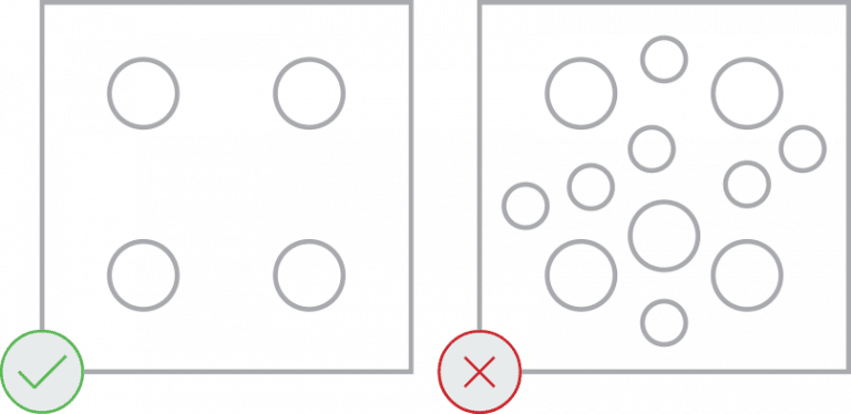
Parts with large amounts of material removal may be impractical for us to produce. Grills, grates, and perforated patterns are not recommended and may be rejected.
We recommend no more than 50% material removed from a given part. The more material that you remove, the greater the risk that your part will move during the cutting process and become damaged.
If you have been designing in CAD for any length of time, you will be familiar with standard fillets. You may be less familiar with another type of fillet commonly used with CNC milling: The “Dogbone” fillet.
A standard fillet is used to reduce the sharpness of corners. You can modify corners with either a chamfer or curve.
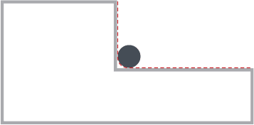

However, for materials that are CNC machined, the inner corners can never be sharper than the diameter of the cutting tool. This is because the tooling is round, and it’s not possible to get perfectly square corners on interior geometry. Instead, these corners will be slightly rounded inwards (approximately .063″ radius). This can cause problems when joining parts, as a part with square edges might not fit in a hole or slot with rounded corners.
Now that you have the knowledge you are ready to start designing your parts for the CNC mill. Questions? Reach out to our support team.
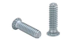
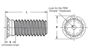
We proudly use hardware by PEM
Aluminum: 5052, 6061, 7075 Steel: Mild
| SKU | FH-M8-12 |
| Thread Size | M8 x 1.25 |
| Hole size in sheet (+0.003/-.0.000) | .315″ |
| Minimum sheet thickness | 0.094″ |
| Maximum sheet thickness | .347″ |
| Fastener material | Steel |
| Minimum distance hole C/L to edge | 0.378″ |
| Minimum distance between two of the same hardware | .567″ |
| Recommended panel material | Steel/Aluminum |
| Coating type | Zinc |
| Length | .472″ |
| Aluminum material ranges (5052, 6061, 7075) | 0.100″-0.250″ |
| Steel material ranges (CRS, HRPO, HR) | 0.104″-0.250″ |
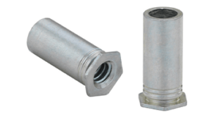
We proudly use hardware by PEM
Aluminum: 5052, 6061, 7075 Steel: Mild, G30
| SKU | SO-440-8 |
| Thread Size | 4-40 x .250″ |
| Hole size in sheet (+0.003/-.0.000) | .168″ |
| Minimum sheet thickness | 0.040″ |
| Maximum sheet thickness | .125″ |
| Fastener material | Steel |
| Minimum distance hole C/L to edge | 0.230″ |
| When determining the distance between two or more fasteners, you can calculate the distance by the formula, C/L to edge + 1/2 the diameter of the second mounting hole. | .345″ |
| Recommended panel material | Steel/Aluminum |
| Coating type | Zinc |
| Length | .250″ |
| Aluminum material ranges (5052, 6061, 7075) | 0.040″-0.125″ |
| Steel material ranges (CRS, HRPO, HR) | 0.048″-0.119″ |
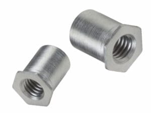
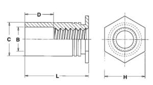
We proudly use hardware by PEM
Stainless Steel: 304, 316
| SKU | SO4-440-8 |
| Thread Size | 440 |
| Hole size in sheet (+0.003/-.0.000) | .166″ |
| Minimum sheet thickness | 0.04″ |
| Maximum sheet thickness | .125″ |
| Fastener material | 400 Stainless Steel |
| Minimum distance hole C/L to edge | 0.230″ |
| When determining the distance between two or more fasteners, you can calculate the distance by the formula, C/L to edge + 1/2 the diameter of the second mounting hole. Example shown with x2 of the same hardware. | .313″ |
| Recommended panel material | Stainless Steel |
| Coating type | Passivated |
| Length | .250″ |
| 304 Stainless Steel material ranges | 0.048″-0.125″ |
| 316 Stainless Steel material ranges | 0.060″-0.125″ |