An L Bracket, also known as an angle bracket, is a type of bracket that typically consists of a single bend at a 90 degree angle equidistant from either side of the unit. An L Bracket also consists of a number of holes that are to attach the brackets with hardware.
Brackets are used for a wide variety of applications in the fields of construction, automotive design and engineering, brackets are a key component to many assembly strategies. In this article we’ll discuss how to prepare a sheet metal L bracket CAD file in Rhino3D.
Metal Bending Process
After being cut with a fiber laser, the flat unit is then prepared to be bent. SendCutSend uses a process called air bending. A line etched into the surface of the unit during the laser cutting process is used as a registering element to confirm where the punch will push the flat unit down into the v-shaped die.
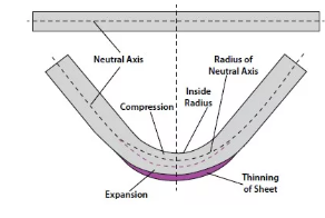
When creating a file for bending it is important to keep in mind that the material will compress on the interior face and expand on the exterior face relative to the neutral axis.
Check out the Guide to K-Factor for more information on the different aspects and terminology related to the bending process.
General Considerations for Bending Metal Brackets
When preparing a file for bending it is important to keep the following general guidelines in mind:
- Maximum flat part size 44″ x 30″
- Maximum bend length 16″ – 44″ depending on material thickness
- Maximum thickness of .250”, depending on flange length
- Holes should not be within the range of the die width used to create the bend to prevent any deformation that may be caused through warping during the bending process. To see which die will be used on your metal piece, see the material page for your selected part material.
For more detailed considerations when preparing your file, refer to the Plastic and Sheet Metal Bending and Forming Guidelines.
8 Steps for Preparing your File for Sheet Metal Bending In Rhino3D
When preparing a file based on a 3D model of a bracket, there are several steps to follow to ensure that the fabricated part matches your expectations.
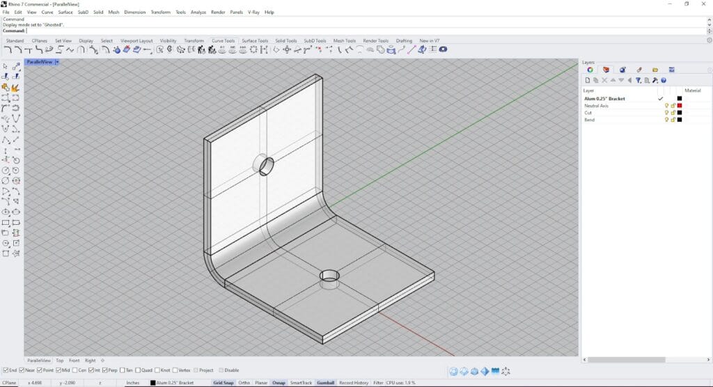
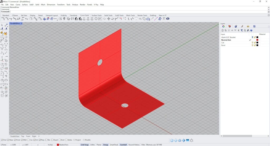
Step 1: Select Bracket Geometry
Identify the geometry that will be prepared as a bracket file. Before beginning, make sure to confirm that the option to be bent is available in your desired material and thickness in the material page “bending” section.
Step 2: Extract Neutral Axis
Using the command “OffsetSrf”, select the “inner” surface of the modeled bracket and offset the polysurface by 40% of the thickness of the material.
For this example, if the material is 0.25” 5052 Aluminum the offset calculation would look like this:
0.25” x (0.40”) = 0.10”
By offsetting the inner surface, the new polysurface that is created acts as an approximation of the neutral axis of the bend. The neutral axis of the bracket is the portion of material that goes through minimal change during the bending process. The material inner side to the neutral axis will be compressed, while the material on the outer side will be stretched.
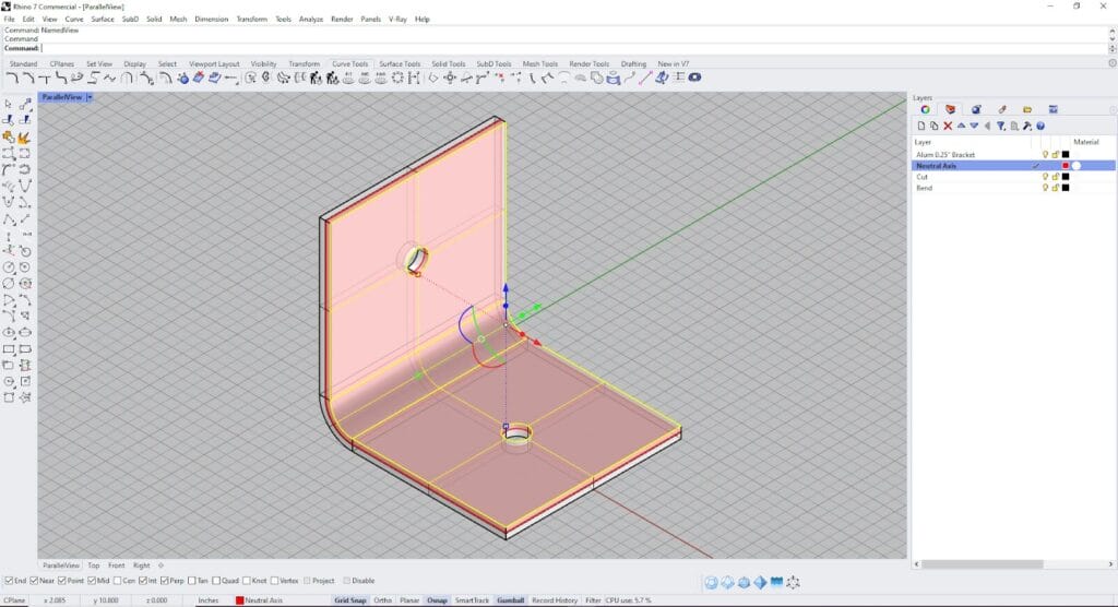
The “inner face” of the bracket geometry is selected and highlighted in yellow.
The neutral axis has been offset and extracted from the bracket geometry.
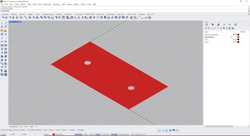
Step 3: Unroll Neutral Axis
Use the “UnrollSrf” command to flatten the neutral surface into a single plane. Select no for all additional command options.
This polysurface geometry will act as the building block for the linework of the bracket file.
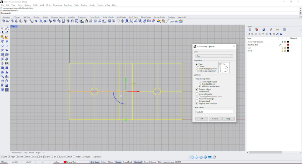
Step 4: Generate Linework
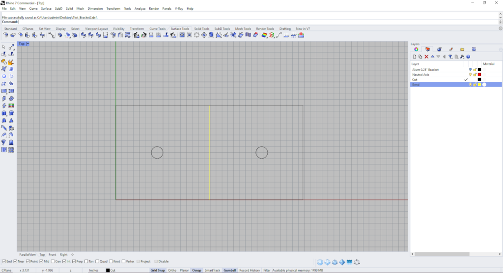
Switch the viewport to the “Top View”, select your geometry and use the command “Make2D” to prepare the linework.
Check the “ Tangent Edges” selection to retain all needed curve profiles.
Step 5: Draw Bracket Bendline
The two lines from the bend portion of the bracket represent the extents of the bend allowance. Find the centerpoint between the lines and draw a curve. This curve will be the bendline for your bracket.
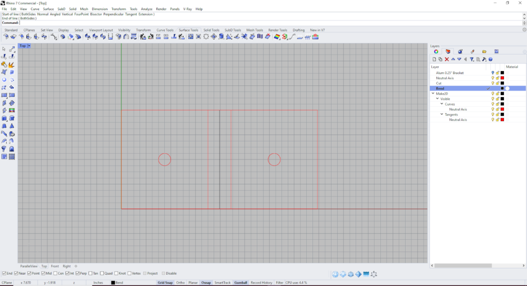
Step 6: Organize your Linework
It is best practice to keep the cutting and bending geometry on separate layers. Organize the linework for the files on layers named “Cut” and “Bend”.
Step 7:Export .DXF File
Select and export your geometry in a .DXF file format.
There are a number of 2D vector-based file types compatible with the SendCutSend app. For a comprehensive list, check out the acceptable file formatting guidelines.
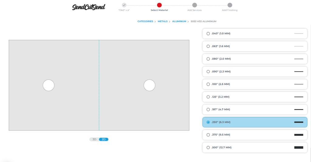
Step 8: Select your Material
After uploading your file, select the desired material type, material thickness and select bending as an additional process. SendCutSend has a handy material selection guide if you need assistance with selecting the best material for your project.
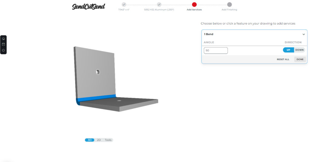
Step 9: Select Bend Type
The “up” and “down” options of the bending process are in reference to how the flange of the unit is oriented in relation to the flat. Make sure that the bend is facing the desired direction.
Including L Brackets in Your Next Sheet Metal Project
Including L brackets in your next project can expand the possibilities of assembly. To add more functional detail to your L bracket project, consider exploring services like countersinking, hardware insertion and tapping.
For another method of creating and checking bends, refer to SendCutSend’s bending calculator .
