
Outranking other aluminum series in yield strength, elasticity, fatigue strength, and hardness, 2024 T3 aluminum can withstand stress and high-impact environments better than most materials. What it lacks in corrosion resistance it makes up for in durability and resilience.
Unlike our other aluminum alloys, 2024 aluminum is alloyed with copper, which is what sets it apart in tensile strength. This unique combination of materials and its resulting capabilities lends laser cut 2024 aluminum to structural, construction, aerospace, and automotive applications.
We recommend our 2024 aluminum for products where strength is of the highest concern. Keep reading for more information regarding the design considerations for laser cut 2024 T3 aluminum.
We source this high-demand metal through trustworthy suppliers with verifiable industry credentials so you don’t have to worry about it. You’ll know that our 5052 aluminum sheets are ready to be transformed into your greatest ideas.
Material certifications (PDF) are available below.
5052 Aluminum .040″
5052 Aluminun .063″
5052 Aluminum .080″
5052 Aluminum .100″
5052 Aluminum .125″
5052 Aluminum .190″
5052 Aluminum .250″
5052 Aluminum .375″
5052 Aluminum .500″
We guarantee awesome quality parts. If you’re not 100% happy, we’ll give you a refund or remake on the spot – no questions, no hassle.
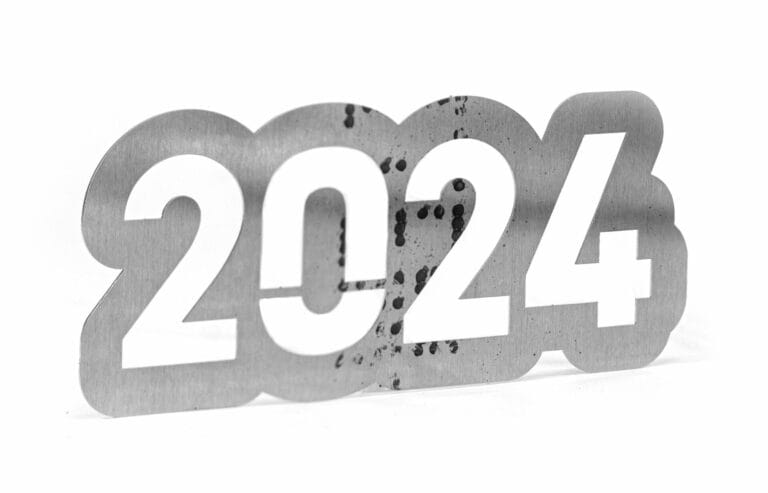
SendCutSend offers 2024 T3 Aluminum in one thickness option: .025″ (.64mm).
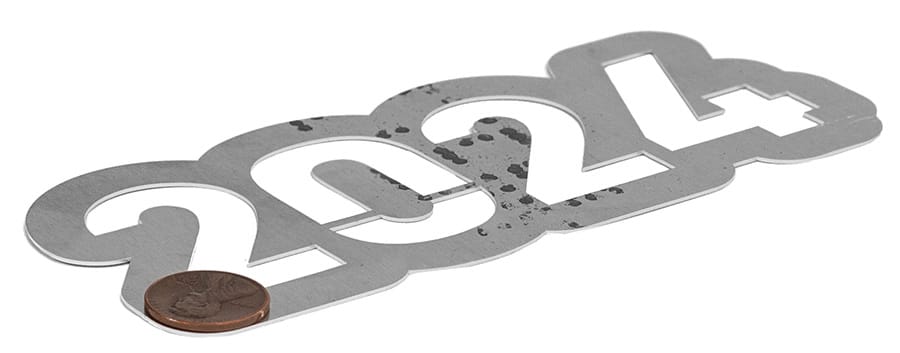
At SendCutSend, 2024 T3 Aluminum is supported with both instant and custom quoting depending on part size. The smallest part allowed is .25″ x .375″, while the largest part supported is 30″ x 44″. For larger projects, custom quotes are available for sizes up to 30″ x 56″.
You can add the following services to your 2024 T3 Aluminum parts:
Laser Cutting
We accept .ai, .dxf, .dwg, .eps, .stp, and .step
Customize one of our simple parts templates

2024 aluminum (often “2024 Al” or “Al 2024”) belongs to the 2xxx series of high-strength aluminum alloys. Its copper + magnesium alloying gives it strength that competes with many steels while preserving light weight. That said, it has tradeoffs, primarily corrosion sensitivity and limited weldability. Below is a full breakdown of what designers, engineers, and fabricators should know when using 2024 in laser cut or sheet metal parts.
Understanding where 2024 fits in requires examining the numbers. Here’s a summary (approximate, varies by temper):
2024-T3 offers an exceptional strength-to-weight ratio, excellent fatigue performance, and moderate ductility, making it ideal for high-load structural parts. However, its corrosion resistance and weldability are limited, so protective coatings or cladding are recommended in most environments.
Among wrought alloys, 2024 is one of the strongest you can get, especially in tension, making it ideal for load-bearing and structural components where weight matters.
One of 2024’s hallmarks is its ability to withstand cyclic loading. That makes it suitable for applications like aircraft skins, structural brackets, fuselage parts, and high-stress joints.
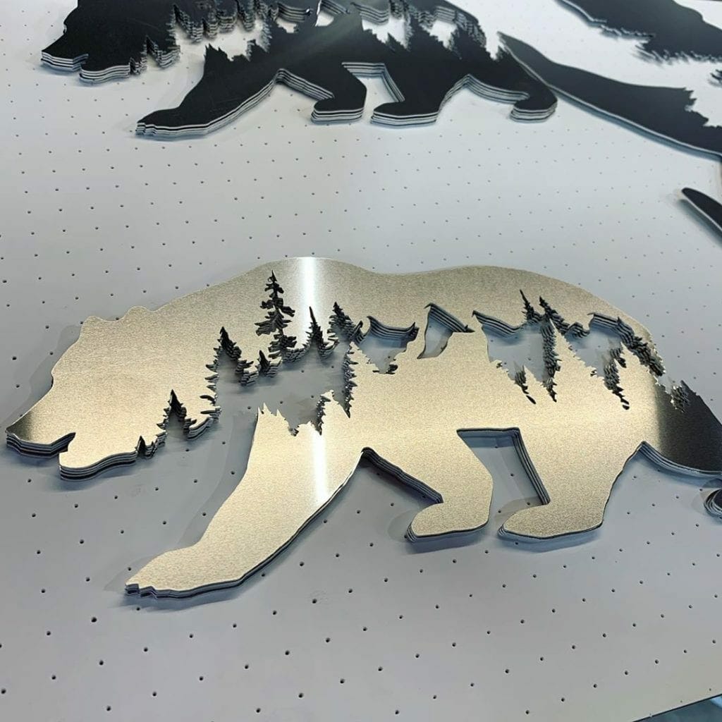
Despite being high strength, 2024 machines reasonably well with the right tooling. You can get tight tolerance features, crisp finishes, and complex geometries when you optimize feeds, speeds, and tooling. And of course, when you have your 2024 aluminum cut at SendCutSend, we handle the feeds, speeds and tooling for you.
Unlike 5xxx and 6xxx alloys (in many cases), 2024 can be heat treated to enhance strength. That gives flexibility: parts are often formed, then heat-treated to final properties.
Because of its performance envelope, 2024 Aluminum is often chosen in aerospace, defense, robotics, and precision gear/structure applications where materials with mid-strength levels won’t cut it.
The copper in 2024 reduces its natural corrosion resistance. Without protection, bare 2024 can pit, stress-corrode, or corrode in harsh environments (salt spray, humidity). Many 2024 sheets are clad with a pure-aluminum skin (Alclad) to help protect the core.
Welding 2024 Aluminum may cause hot cracking, reduced strength at the weld zone, or grain boundary issues. Because of its copper content, 2024 is generally considered more “weld-sensitive.”
While 2024 is ductile enough for many designs, it’s less forgiving than softer aluminum alloys like 6061 T6 Aluminum or 7075 T6 Aluminum in bending or forming large deformations. Some tempers may crack under aggressive forming.
The same “2024” alloy can perform quite differently depending on temper (T3 vs T4 vs T351), so design assumptions must be conservative or based on exact specs. At SendCutSend we stock 2024 T3 Aluminum.
When fabricating parts in 2024 Aluminum, especially via laser cutting or sheet metal, here’s what to watch for:
Because of its strength, fatigue behavior, and aerospace pedigree, 2024 is used in:
If your design calls for cutting 2024 parts, the justification often comes from needing strength beyond what 6061 or 5052 can reliably supply in that geometry.
2024 aluminum offers a performance tier above more common alloys—its strength, fatigue resistance, and ability to be heat-treated make it ideal for structural, high-stress, and aerospace-grade parts. Yet, you accept tradeoffs in corrosion resistance, weldability, and handling complexity. Designers who pick 2024 are often doing serious work. They expect material behavior, tolerances, and finishing to all align.