Designing projects in a CAD software like Autodesk Fusion makes utilizing SendCutSend’s laser cutting service easy. After your design is complete, the first step to uploading parts to our instant pricing tool is learning how to export a DXF in Autodesk Fusion. Watch the video or follow along with the transcript below to learn our best tips for this.
Be sure to export your designs in either millimeters or inch units; we have guidance on how to change units in Fusion here.
Video Guide and Tutorial on Exporting to DXF from Fusion
What is Autodesk Fusion’s Flat Pattern Mode?
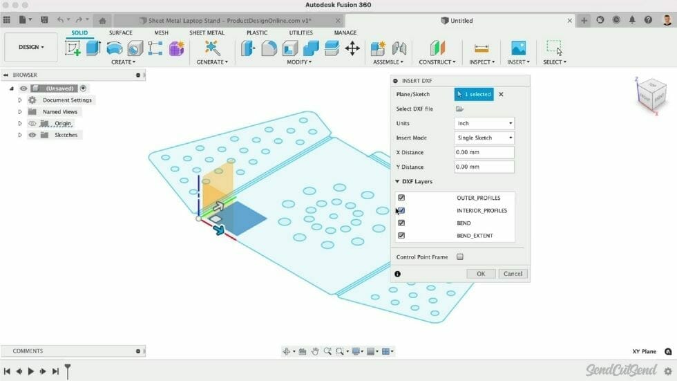
Exporting a DXF from Autodesk Fusion’s Flat Pattern mode has some advantages and disadvantages when it comes to laser cutting. The DXF will include all outer profiles, interior profiles, bend center lines, bend extend lines, and any text, which will all be assigned to different layers within the DXF file.
Getting started with exporting a DXF in Autodesk Fusion
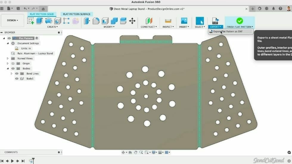
With the Flat Pattern active, we can select “Export Flat Pattern as DXF.”
You will then see the option to “Convert Splines to Polylines.” Polylines are line segments strung together, which makes them much simpler. This option is recommended as polylines are more widely accepted and provide more consistent results across software packages.
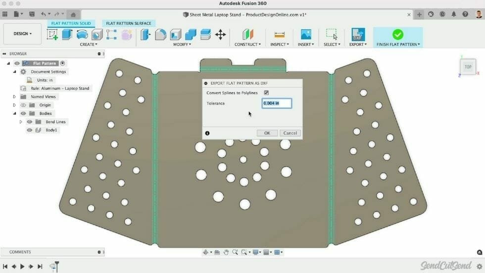
After checking the option, we can also define the tolerance. This will specify the maximum allowable deviation between the polylines and the original splines. Leaving this to the default is often sufficient.
After clicking OK, we’re presented with another dialog where we can define the File name and location. Click Save once you’ve filled out the name and location.
Tips for how to export a DXF in Autodesk Fusion
We also recommend opening your DXF file in a graphics program, such as Adobe Illustrator, or reopening the DXF in a new Autodesk Fusion file to ensure everything is exported as expected.
The only real disadvantage to this Flat Pattern Export is that it will always include the bend lines and Autodesk Fusion does not currently have a choice to exclude them. You may choose to remove them in a graphics program or separate Autodesk Fusion file, to ensure they’re not confused with the outer contour lines. (However, if you are also utilizing SendCutSend’s online CNC bending service and you export a DXF in Autodesk Fusion, we require that you use the default bend line indicators that Autodesk Fusion provides.)
| SOFTWARE | FORMAT | BEND LINE |
| Fusion | .dxf | Solid line (default) |
| Adobe Illustrator | .ai | Solid, separate color from cut lines |
| SolidWorks | .dxf | Dashed line (default) |
| AutoCAD | .dxf | Dashed line |
| CorelDraw | .eps | Solid, separate color from cut lines |
| Inkscape | .eps | Solid, separate color from cut lines |
Final thoughts on Autodesk Fusion’s Flat Pattern feature
To summarize, leveraging Autodesk Fusion’s sheet metal features are a great way to design for sheet metal manufacturing while providing flexible workflows. Creating custom Sheet Metal Rules allows you to design specific to the material and bend processes you’re working with. And exporting the Flat Pattern as a DXF is a quick and easy way to get a flat pattern for laser cutting.
If you have any other questions about how to export a DXF in Autodesk Fusion or other CAD programs, be sure to check out our other blog posts or reach out to our support team.
