There are many ways to export part designs from Autodesk Inventor, but DXF and STEP files work best with SendCutSend’s instant pricing system for laser cut parts.
In this guide, we’ll cover
- how to export Inventor designs to the DXF and STEP file formats,
- when exporting to DXF or STEP makes the most sense,
- and important file setup requirements to meet before finalizing your design
Let’s get inventive!
Design considerations with Inventor
Use units we accept and 1:1 scale
Whether you export a DXF or STEP format file from Inventor, plan to use units of measurement we accept and set up your file in 1:1 scale.
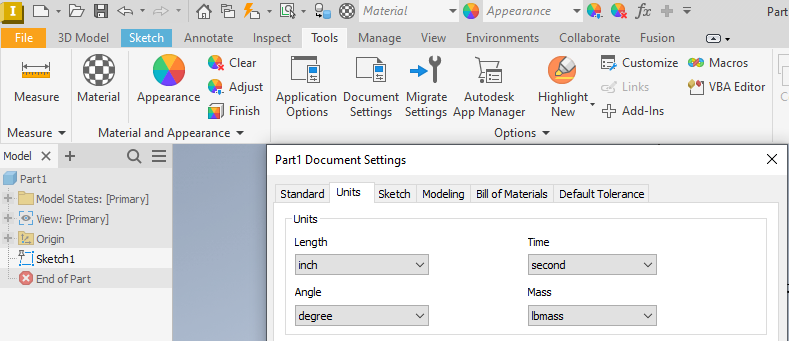
Design your part using either inch or millimeter units. You can update the units for your Inventor project by navigating to the Tools tab, opening Document Settings, and choosing either inch or millimeter from the drop down menu before clicking Apply.
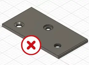
Do not model 3D cut features in sheet and plate parts
Sheet or plate parts that will be cut using one of our 2D cut methods (laser cutting, waterjet cutting, or CNC routing) should not have 3D features like counterbores or chamfers modeled.
If you need tapping, countersinking, dimple forming, or hardware insertion services, please add simple through-holes only.

You’ll be able to call out needed tap, countersink, dimple, or hardware sizing by configuring your part in our instant pricing system. Learn more about why we don’t require traditional mechanical drawings with callouts.
See our full Design Guidelines for more considerations when setting up your part designs.
Exporting DXF files from Inventor
Exporting a DXF file from Inventor is the way to go if you’ve designed entirely in the 2D sketch space, or you’ve modeled flat parts in 3D that won’t require bending services.
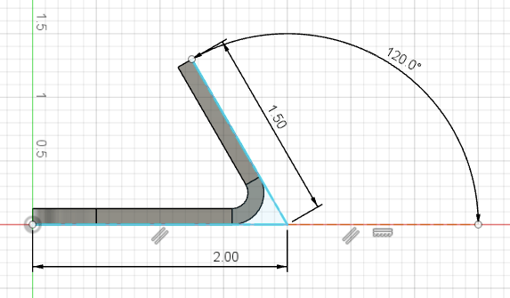
If you sketch a part with bends, start by using our Bending Calculator to ensure the flat dimensions you draw will result in the formed dimensions you want. Each material thickness we bend has a preset inside bend radius and K factor that cannot be changed. You can confirm the bend radius and K factor for each material thickness in our handy chart or in the Material Catalog.
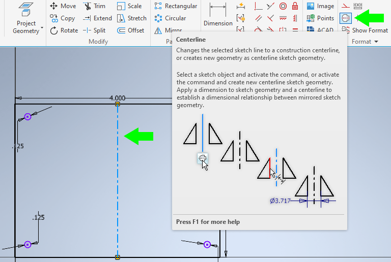
To draw your bends, indicate the center of each bend with a line and apply the Centerline setting to make it dashed. Your bend location line will indicate where the press brake’s punch contacts the part in order to form the flange.
Exporting sketches to DXF
When your sketch is ready, follow these steps to export a DXF file that will be interpreted accurately by our instant pricing system.
1. Select your sketch (all sketch geometry should highlight blue).
2. Right click and choose Export Sketch As.
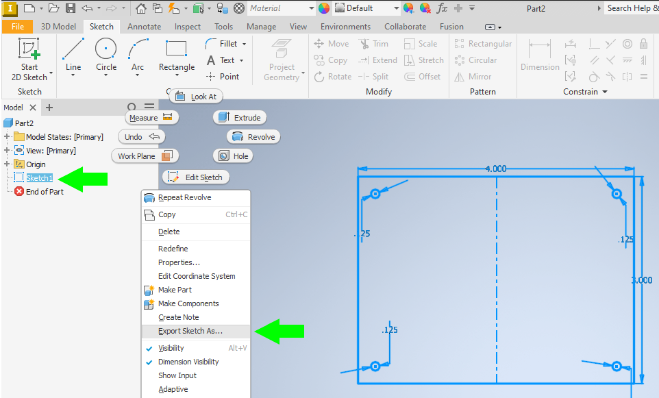
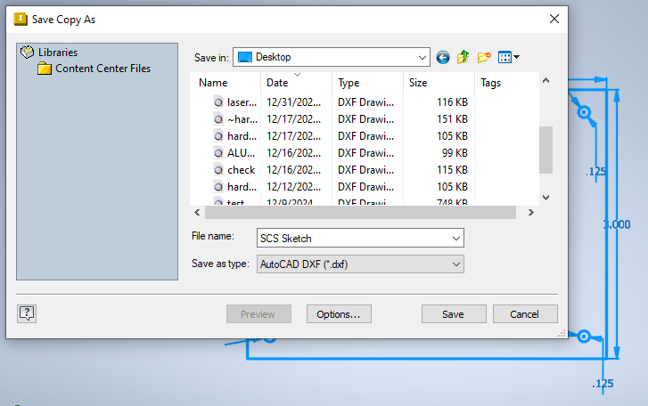
3. Save as type: AutoCAD DXF.
4. Click Save.
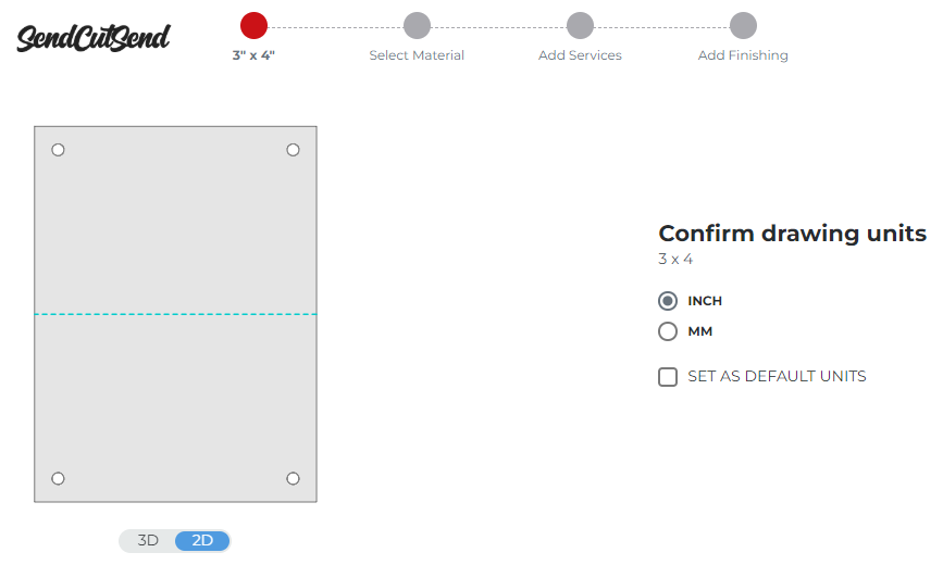
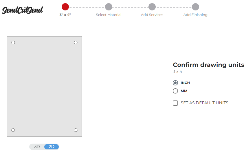
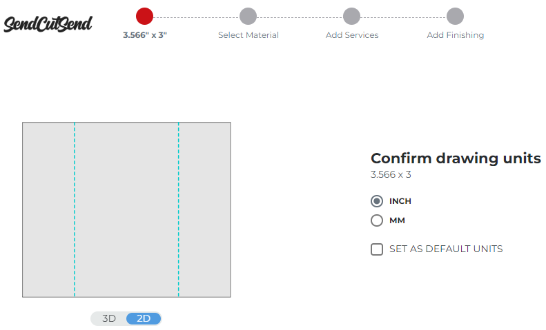
Your part should upload successfully and show the correct overall dimensions!
If you added bend lines, they should show as blue dashed lines. After selecting a material thickness that we bend, you’ll be able to configure the bend angle and direction for each bend line at the Add Services step in our pricing system.
Exporting flat models to DXF
If you’ve modeled a part that won’t require bending services, exporting to DXF is a good option!
1. Right click on the main surface of the modeled part.
2. Click Export Face As.
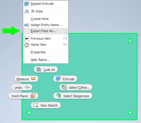
3. Save as type: AutoCAD DXF.
4. Click Save.
Your part should upload successfully and show the correct overall dimensions!
Exporting bent models to DXF
If you model a bent part in 3D that meets our guidelines but you see an error when attempting to upload a STEP file, exporting to DXF is a reliable alternative.
Keep in mind that even if you export a modeled bent part to DXF, all 3D file considerations detailed in the section below still apply. If your model does not use the correct bending specifications for the material needed, your exported flat pattern will not be accurate.
Read on to learn about 3D file setup – we’ll explain how to export a bent model to DXF if a STEP upload doesn’t work!
Exporting STEP files from Inventor
Exporting a STEP file from Inventor is best if you’ve designed using the 3D modeling tools to create parts that will require bending services.
Review our 3D File Guidelines before exporting a STEP file to ensure your design meets all requirements and uploads to our website successfully!
Use SendCutSend’s bend radius and K factor
For bent parts, it is critical that modeled designs are set up as sheet metal parts using our bending specifications for the intended material. Your part should use a sheet metal rule that matches our material thickness, inside bend radius, and K factor specifications.
If bent parts are not set up using our material specifications, the final formed dimensions are unlikely to match your intended design. You can confirm the bend radius and K factor for each material thickness we bend in our spec chart or in the Material Catalog.
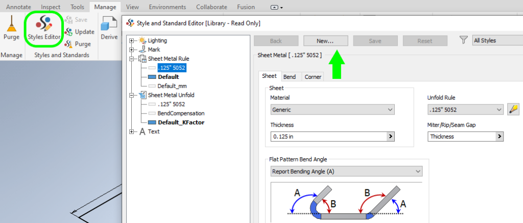
You can create new sheet metal rules in Inventor by navigating to the Manage tab, opening the Styles Editor, selecting the default rule, and then clicking New.
You’ll need to set up a new Sheet Metal Rule and corresponding Unfold Rule (K factor) for each material thickness desired.
Tip: if you have access to Autodesk Fusion, consider using Fusion to design your bent sheet metal parts. Then you can take advantage of our free pre-configured sheet metal rules and save time! Learn how to download and import our sheet metal rules for Autodesk Fusion.
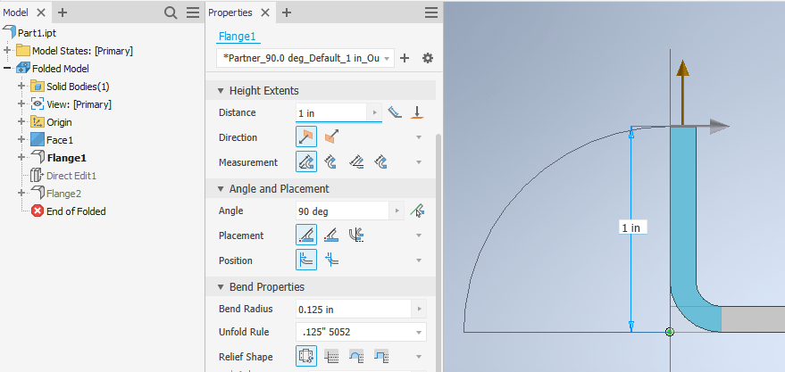
Flange considerations
When you add flanges to parts, ensure the correct sheet metal rule and settings are applied.
Our specifications and bending calculator are set up with the expectation that formed flange dimensions are measured from the outside and to the apex of the bend.
Flange properties should be the following:
Measurement: from intersection of two outer faces
Placement: plane through partner edge
Position: outer face through plane
Bend radius: matches SendCutSend bend radius for material thickness
Unfold rule: rule matches K factor for material thickness
Exporting sheet metal parts to STEP
When your sheet metal part is ready to export, click File, then Export, and then select CAD Format.
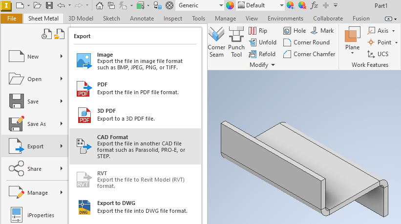
Save as type: STEP Files.
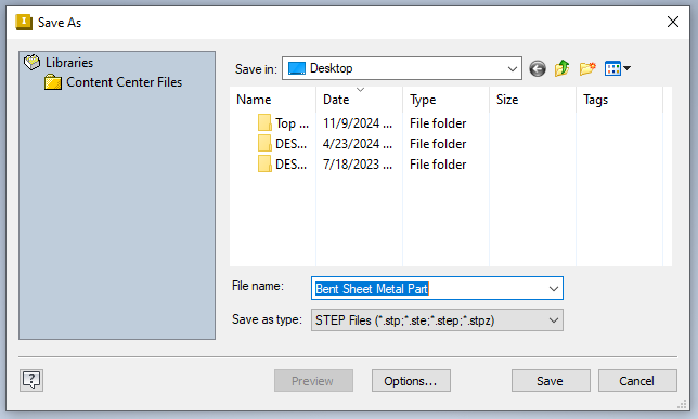
If you set your part up using a correctly configured sheet metal rule, your STEP file should upload successfully and without errors!
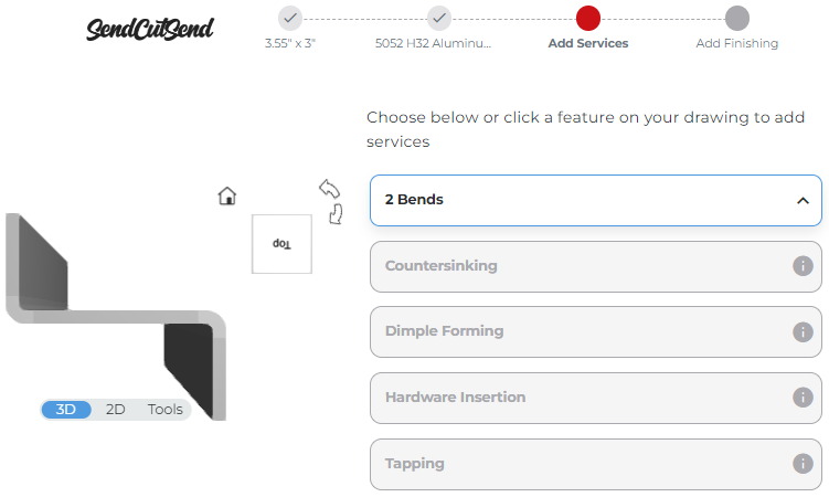
Please note: whether you design in inches or millimeters, our app will display overall flat (pre-bend) dimensions for STEP files in inches.
Our pricing system should automatically detect the bends you modeled, including the degree and direction for each. We recommend reviewing your part’s bend definitions at the Add Services step to ensure everything is correct before checking out!
Receiving errors? Export your model to DXF instead
As mentioned above, if your STEP file meets our 3D guidelines but still receives errors upon upload to our website, you can export to DXF instead.
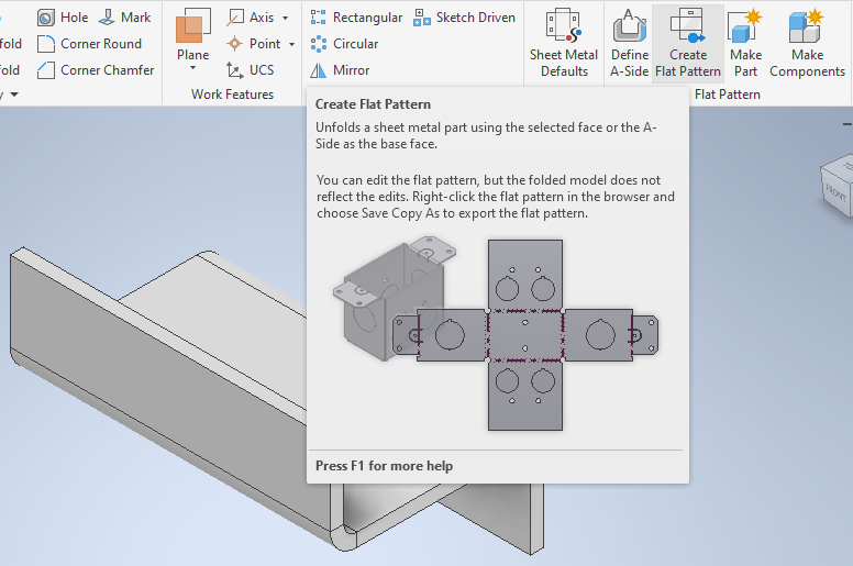
After your model is set up with our sheet metal specifications and the design is finalized, click Create Flat Pattern.
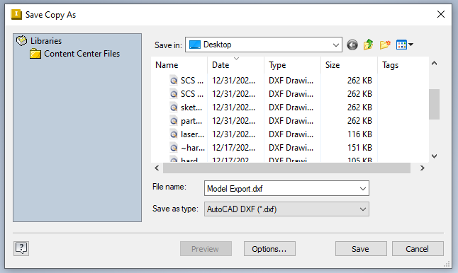
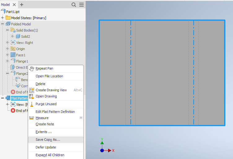
When your flat pattern is created, right click on Flat Pattern and then choose Save Copy As.
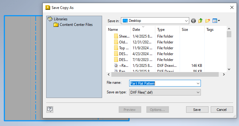
Then Save as type: DXF Files
A window will open for Flat Pattern DXF Export Options.
Under the Geometry tab, the Replace Splines box should be ticked with Linear Approximation selected and a tolerance of about 0.010 inches. This setting works well for most files and should be the default.
In the 2d Geometry options, you can tick the Merge Profiles into Polyline and Rebase Geometry to 1st Quadrant options if you like, but they’re not required.
Do not tick the Trim Centerlines at Contour box. This will trim any bend lines that cross over holes or cutouts in your design, which can result in one bend being read as multiple bends by our pricing system.
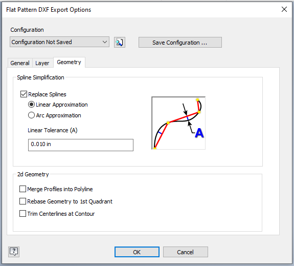
If you leave the Trim Centerlines at Contour box unchecked, each flange should be interpreted correctly even if there are cutouts.

Click OK to save your DXF.
When you upload your file, the bend lines should be recognized automatically. From there you can proceed to get instant pricing and configure bending services!
What’ll you invent next?
Remember, when exporting from Autodesk Inventor:
- use units we accept (inches or millimeters) and set up your part in 1:1 scale
- do not sketch or model taps, countersinks, dimples or hardware; instead create simple through holes you’ll configure in our pricing system with any needed hole operations
- export a DXF format file if you’ve sketched your part in 2D, or modeled a flat part
- export a STEP format file if you’ve modeled a part that requires bending services
- before exporting a STEP file, ensure your part is set up using SendCutSend’s bending specifications for the material thickness you plan to use
Whether you export DXF or STEP format files from Inventor, we’re here to make your laser cutting projects faster and more affordable than anywhere else! Be sure to review our service guidelines before finalizing your part design and uploading to our website. Don’t hesitate to ask our Support team if you have questions!
