The Bend tool in Autodesk Fusion lets you preview how your sheet metal part will look once bent and confirm the final formed dimensions. To use it correctly: (1) set up a sheet metal rule with the right K factor and bend radius, (2) sketch your flat pattern with bend lines, (3) extrude using the Flange tool, (4) apply bends with the Bend tool, and (5) measure the 3D model to confirm dimensions before exporting a DXF.
Why Use the Bend Tool?
The Bend tool allows you to simulate bends in 3D, ensuring your part will form as expected after manufacturing. It applies the sheet metal rule (bend radius + K factor) so your Fusion model’s dimensions align with what SendCutSend will cut and bend.
Step 1: Create a Sheet Metal Rule
Before bending, define a rule for your material and thickness:
- Go to Sheet Metal > Modify > Sheet Metal Rules.
- Create or edit a rule with the correct material thickness, bend radius, and K factor.
- Use the values from our Bending Calculator and Bending Specifications.
➡️ This ensures your model matches SendCutSend’s real-world forming process.
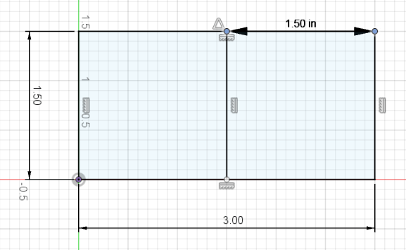
Step 2: Draw a 2D Sketch with Bend Lines
- Create a flat pattern sketch using the dimensions from the Bending Calculator.
- Add bend lines at the center of each bend location.
- Keep bend lines continuous/solid; Fusion will handle line formatting automatically on export.
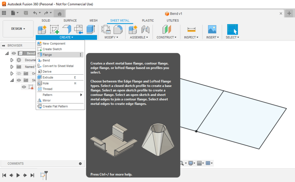
Step 3: Extrude with the Flange Tool
Instead of a standard extrude, use the Flange tool to create a sheet metal body:
- Go to Sheet Metal > Create > Flange.
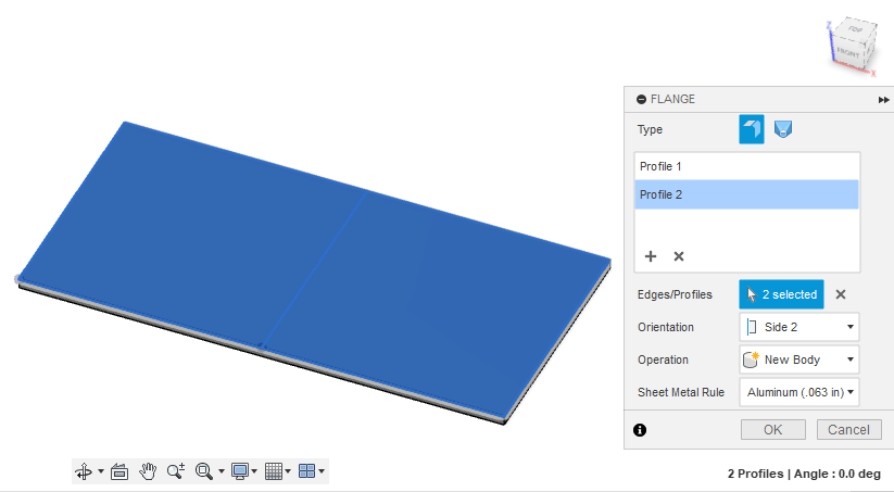
- Select all profiles.
- Set Orientation to Side 2.
- Choose your Sheet Metal Rule.
- Click OK.
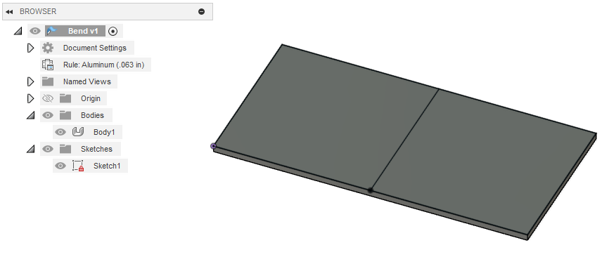
➡️ The Flange tool automatically converts your sketch into sheet metal and applies the rule.

Step 4: Add Bends Using the Bend Tool
Now you can bend your design:
- Un-hide your sketch (eye icon).
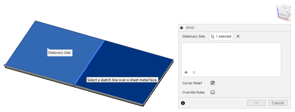
- Go to Sheet Metal > Create > Bend.
- Select a stationary side.
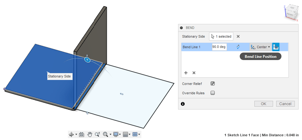
- Select bend lines where you want bends applied.
- Set Bend Line Position to Center.
- Click OK.
You can re-hide the sketch afterward. The Bend tool will apply your sheet metal rule and show accurate formed dimensions in 3D.
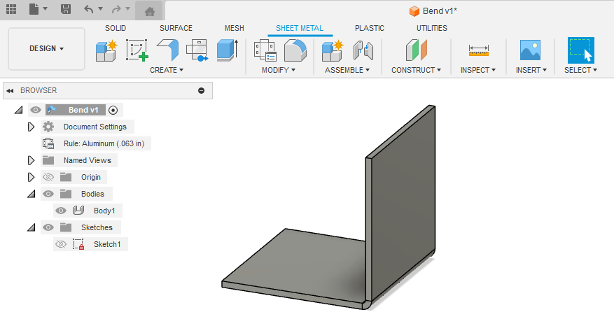
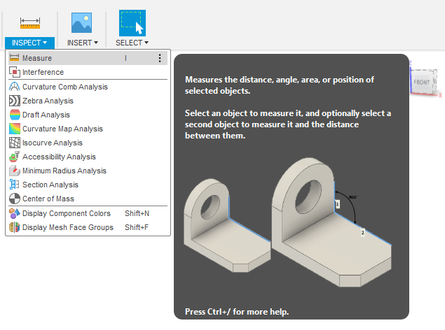
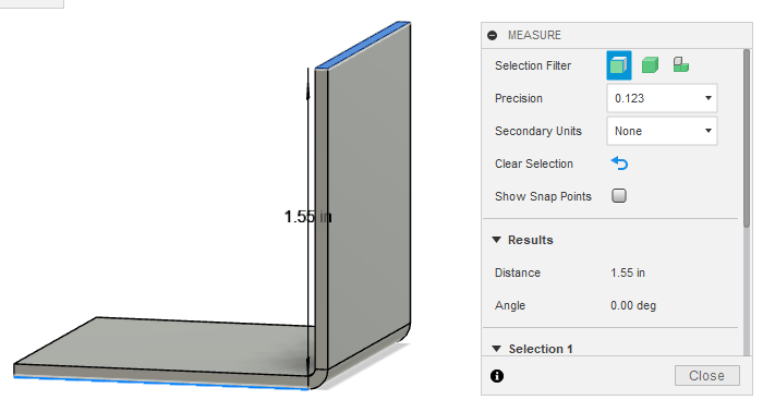
Step 5: Measure Your 3D Part
- Use the Measure tool to check the formed dimensions of your bent part.
- Fusion applies your sheet metal rule automatically, so the preview should match real-world dimensions.
Example: A flat pattern designed per the calculator may form to a final bent height of 1.55” in Fusion.
Export Your Flat Pattern DXF
When you’re ready:
- Export a flat pattern DXF (not a 3D body).
- Follow our guide: How to Export a DXF from Autodesk Fusion.
- The exported DXF will match your original flat sketch dimensions.

Quick Recap
✅ Measure the 3D part, then export the flat pattern DXF.
✅ Set up a Sheet Metal Rule with SendCutSend’s bend data.
✅ Sketch your part and mark bend lines.
✅ Use the Flange tool to create a sheet metal body.
✅ Apply bends with the Bend tool, using Center line position.