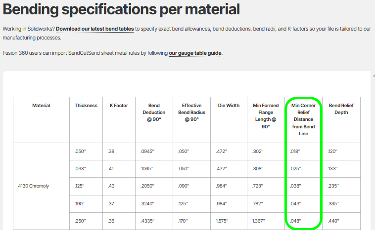
To keep perpendicular flanges from clashing in a corner, use our Min Corner Relief Distance from Bend Line spec (pictured below). If the clearance between bend lines meets or exceeds that value for your chosen material thickness, you’re in the clear.
When perpendicular flanges meet, like in a box corner, they can bump into each other and stall production. Building in enough clearance from the start saves headaches later.
1. Use our bending specification table
- Look up the Min Corner Relief Distance from Bend Line for your material thickness in our bending specification table.
- This spec is different from the Bend Relief Depth — both matter, but they solve different problems.
- Learn how to apply the Bend Relief Depth spec in our bend relief requirements article
2. Check your design
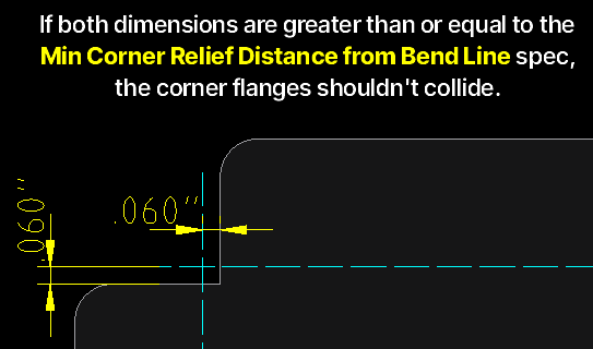
- Extend each bend line past the flange edge.
- Measure from each bend line to the edge of the other flange.
- If that distance is equal to or greater than the Min Corner Relief Distance for your material thickness, the flanges won’t collide.
Pro tip: our Min Corner Relief Distance from Bend Line spec is calculated as follows:
Formula for the spec:Material Thickness – (Bend Deduction @ 90° ÷ 2) + 0.015”
Find Bend Deduction values in our Bending Calculator or Material Catalog.
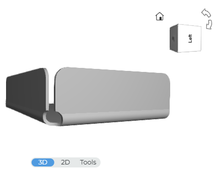
3. About the 3D preview
Our pricing system’s 3D preview is a good visual reference, but it can’t guarantee collision-free corners. Designing with the proper clearance is the only sure way.
4. CAD tips
- In 2D CAD, clearance checks are especially important.
- In 3D CAD, set your material thickness, bend relief, and K factor to our specs. We offer free Fusion 360 Sheet Metal Rules and [SolidWorks Gauge Tables] to load them in with just a few clicks.
Bottom line:
If your design matches or exceeds the Min Corner Relief Distance, your flanges will form cleanly without interfering.
As always, if you have questions about clearance or other design requirements, reach out to our Support team anytime!