Bending sheet metal and plastic is a transformative step in manufacturing, turning flat sheets into strong, functional, 3D parts. However, whether using steel, aluminum, or polycarbonate, the key to consistently accurate results is understanding bending tolerances, material guidelines, and best practices for file setup. This SendCutSend guide distills everything you need to know—direct from our bending FAQs—to help engineers, designers, and makers get production-ready results without surprises.
Overview of Bending Guidelines
At SendCutSend, bending success starts with clear, material-specific guidelines. Each metal or plastic has unique bend radii, tolerance, and design requirements you must factor into your files. By following our guidelines—available in the SendCutSend Material Catalog and through the Bending Calculator—you’ll avoid common mistakes, minimize revisions, and ensure your finished parts match your intended function and fit.
Key Bending Requirements for File Setup
To optimize your project for bending:
- Use accepted design file formats (.dxf, .dwg, .ai, .eps for 2D; .step, .stp for 3D)
- Clearly mark bend lines, following the file guidelines for center or edge lines
- Apply the correct bend radius and K-factor for each material
- Ideally, use the [SendCutSend Bending Calculator] to confirm your specs before uploading for quote or manufacture
Understanding SendCutSend Bending Tolerances
Bending tolerances refer to the allowable variation in bend angles, flange lengths, and finished part dimensions. These tolerances ensure function, provide design flexibility, and give you realistic expectations for what can be held in manufacturing.
Sheet Metal Bend Angle Tolerances
- Bends up to 24”: ±1°
- Bends longer than 24”: ±2°
Plastic (Polycarbonate) Bend Angle Tolerances
- Bends up to 24”: ±5°
- Bends longer than 24”: ±7°
Dimensional Tolerances and Stackup
- Single flange: ±0.015” (bend to edge)
- Two parallel bends: ±0.030”
- Add ±0.015” for each additional flange
Understanding these limits helps you design parts that are robust, manufacturable, and ready for real-world use.
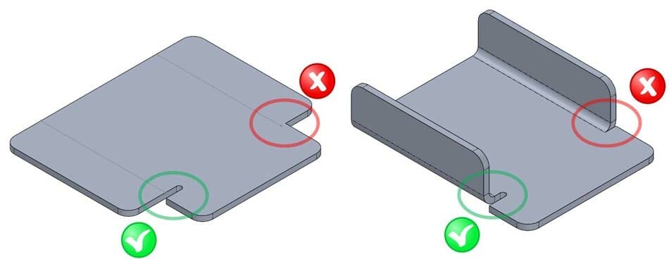
Bend Relief Best Practices
Bend reliefs are critical features that prevent tearing and deformation near bend lines. Proper size, shape, and placement of these notches allow metal to flex without damage, extending part durability and maintaining clean bends.
1. Why bend reliefs matter
Without reliefs, the inner bend radius takes the full forming stress. This can:
- Cause corner bulging
- Tear the material at the bend
- Distort adjacent features
By adding reliefs:
- Stress is distributed evenly
- Flanges form cleanly
- Corners keep their intended geometry
2. Minimum bend relief size
For most materials, relief notches should be:
- Width: ≥ 50% of material thickness
- Depth: Bend radius + material thickness +
0.020"
📄 See our Bending Deformation Guidelines for more on relief placement and its effects.
3. Polycarbonate bend relief requirements
Polycarbonate is prone to cracking if reliefs are missing or undersized.
- Reliefs must be rectangular
- Must meet the minimum bend relief depth for your thickness
- Specs are listed on our Polycarbonate Material Page
If your polycarbonate design doesn’t meet relief specs, it’s likely to fail during forming.
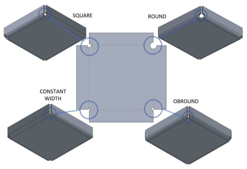
4. Sheet metal bend relief recommendations
- Reliefs are optional for thinner metals, but we strongly recommend them for materials 0.187” and thicker
- You can use any relief shape you prefer (rectangular, circular, narrow notch)
- Even with thin materials, reliefs improve aesthetics by reducing corner distortion
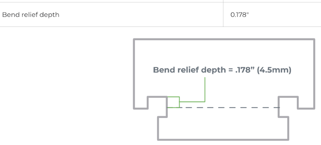
5. How to measure bend relief depth
On your flat pattern:
- Locate the bend line (center of the bend)
- Measure from that line to the bottom of the relief notch
- The distance should meet or exceed the minimum depth spec for your material

6. Alternative to adding a relief
If possible, move the bend location so it no longer needs a relief. This can be a quick fix that maintains part strength while avoiding extra geometry.
Channel Bend Requirements
Channel bends require careful design consideration of minimum flange lengths and proper spacing to create strong, functional U-shaped parts. Understanding SendCutSend’s channel bend guidelines protects against structural issues and ensures precise, repeatable bends.
Polycarbonate channel bend requirements
Require a base-to-flange ratio of at least 3:1 to prevent cracking and maintain formability

Learn more about polycarbonate bending considerations.
Sheet metal channel bend requirements
A standard ratio is 2:1 base-to-flange, but for thinner sheet metals (≤0.135”), we may allow as small as 1:1 if flanges don’t exceed 3” and bases are at least 1”. The thicker the metal, the firmer the base and flange requirements.

Best Practices for Smallest Possible Bases in Consecutive Bends
When designing multiple parallel bends, the spacing between bend lines depends on the bend angles and material specs. For most situations:
- If both bends are 5–45°, use minimum joggle “bend-to-bend” spacing for your thickness
- For steeper angles, multiply minimum flange length or acute bend center spec as outlined for your material
Designing within these limits maintains part accuracy and prevents interference or deformation during bending.
For more in depth details about SendCutSend channel bend requirements, reference our channel bend requirements FAQ.
Joggle Bend Requirements
Joggle bends—parallel bends in opposite directions placed closely together—require special care. Minimum and maximum allowable distances between joggles depend on angle and material die (see your material’s spec page). For polycarbonate, joggles are possible if bends are at least 3” apart (apex-to-apex) and within 45–90°.

Bending Parts with Odd Flange Shapes
For irregular flange designs, a flat, parallel reference edge along the bend line ensures clean bends and avoids deformation. If a flat edge is impossible, break-off tabs may be used (and then removed post-bending). Follow best practices for tab size and placement, and be aware that polycarbonate tabs should be cut, not snapped, to avoid cracking.
You can:
- Revise your design to create a flat edge, or
- Add break-off tabs (material extensions with connecting bridges) that are removed after you receive the part.
Note: We don’t remove break-off tabs. If you add finishing services, the raw edge beneath the tab will be visible after removal.
Break-off tabs give you the flexibility to keep your original flange shape while still meeting our bending setup requirements.
Measuring Bent Parts Correctly
Accurate measurement of flange lengths, especially on bent parts, is essential for quality control. Learn how to measure from the bend apex and use the correct reference points to verify part dimensions.
Flange length is measured from the center of a bend to the nearest cut edge. Each material thickness has a minimum flange length specification that must be met in order for us to bend parts. How you measure flange length typically depends on whether you design your parts in a 2D or 3D design software program.
Learn how to find and apply our minimum flange specifications in either case!
Defining the base, flange, and apex
Base, flange, and apex are fundamental bending terms to know before discussing flange length.
Base: the stationary area of your part
Flange: the edge that is bent away from the base
Apex: where the bend occurs (the very center of the bend)

For a deep dive on bending terms, see The Ultimate Guide to Bending Terminology.
Defining flange length
Flange length is the distance from the bend line to the closest cut edge of the part.
The “bend line”, apex, or center of the bend is where the CNC brake’s punch will make contact with the material and form the flange.
A minimum amount of material is required on either side of where the punch will make contact in order to provide support for the bend operation. If there is too little material, the part will deform or even twist during the bending process.
Measuring flange length
Flange length on a 2D flat pattern
If you are measuring flange length on a two dimensional flat pattern, measure from the bend line to the nearest cut edge.
Use our Bending Calculator to make sure that your flat 2D design will result in the final, formed dimensions you want. The flat pattern should account for material stretching that occurs during the bending process.

Flange length on a 3D model
If you create your parts in a 3D modeling design software like Autodesk Fusion or SolidWorks, measure flange length from the apex of the bend.
To ensure that your measurements are accurate, set up your model as a sheet metal part and use our material specifications in your sheet metal rules.
You can find all material specifications for bending in our Bending Calculator Specifications Chart.
We accept STEP and STP format files for quoting, so you can upload them directly to our quoting system. Just make sure your part design file meets our 3D File Guidelines!
Best Practices for Bending Success
- Set up sheet metal rules in your CAD program with SendCutSend specifications: use appropriate bend radius, K factor, and flange parameters
- Always use the Bending Calculator or consult the Material Catalog to confirm specifications before uploading
- For multi-bend or box designs, account for tolerance stackup and dimensional changes
- Check all design files for proper feature spacing, relief notches, and format per the above requirements for smooth production
Essential Tips for Successful Bending
Preparing files according to these detailed bending guidelines ensures the highest quality results and speedy turnaround from SendCutSend. Explore the Bending Calculator, read through specific FAQ articles, and consult the Material Catalog for the most up-to-date, material-specific parameters.
For more help, review SendCutSend’s Design and Bending Guidelines, or reach out directly with your custom project questions for personalized support.


