Our channel bend (also known as u-channel or c-channel) requirements depend on the material, stock thickness, and part design geometry. Read on to learn about our general and specific limitations for these types of bends!
Polycarbonate channel bend requirements
Polycarbonate u-channels must have a 3:1 base-to-flange ratio.
Learn more about polycarbonate bending considerations.
Sheet metal channel bend requirements
Sheet metal u-channel parts generally require a 2:1 base-to-flange ratio.
There can be exceptions for designs in thinner materials with specific dimensions. Before we get into more flexible materials, please note that some parts will always be subject to firm limits.
Channel limits for thicker sheet metals
U-channel parts in material thicker than 0.135” must have a 2:1 base to flange ratio.
For u-channels in 0.187” – 0.250” thick sheet metal, the base of the u-channel must be no smaller than 2x the Min flange length (before bend/Flat Pattern) 90° or less (obtuse).
Confirm this specification on your chosen material’s page.
Exceptions to the 2:1 ratio rule for sheet metal parts
The 2:1 ratio rule can be flexible for thinner sheet metal materials that meet specific criteria.
1:1 ratio u-channel limits for sheet metals up to 0.135″ thick
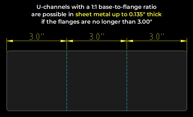
For sheet metals up to 0.135” thick, if the u-channel’s flanges are no longer than 3.00”, the part can have a base to flange ratio as small as 1:1.

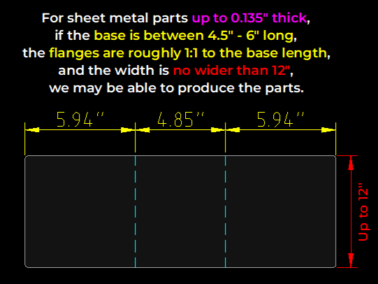
For sheet metals up to 0.135” thick, if the u-channel’s base length is between 4.5″ and 6.00″, the flanges are roughly 1:1 to the base length, and the part is no wider than 12″, we may be able to produce the part.

Less than 1:1 ratio u-channel limits for sheet metals up to 0.125″ thick
For sheet metals up to 0.125” thick, if the base is at least 1.00” wide and the flanges are no longer than 3.00”, we may be able to bend channels smaller than 1:1.

Smallest possible base for consecutive, parallel sheet metal bends
In this section we’ll cover the smallest possible distance between two parallel sheet metal bends that are bent in the same direction. These are different from joggle bends which are two parallel bends in opposite directions. See our writeup on joggle bend requirements if needed.
Calculate if there is sufficient space between two parallel bends in the same direction depending on the bend angles. Find the specifications cited here on each material page.
When setting up small parts for bending, keep our minimum flange length and minimum flat part size requirements in mind as well.
Both bends are between 5° – 45°
If two parallel flanges are bent between 5 – 45 degrees in the same direction, they must be at least the Minimum joggle Bend line to bend line @90° max flange specification for the material thickness apart. Measure from bend line to bend line.
One or more bends is between 46° – 90°
If one or more flanges is bent between 46 and 90 degrees and neither bend exceeds 90 degrees, multiply the Min flange length (before bend/flat pattern) 90° or less (obtuse) specification for the material thickness by 2.
That value will be the minimum distance needed between parallel bends in the same direction if one or more bends is between 46 and 90 degrees. Measure from bend line to bend line.
One or more bends is between 91° – 130°
If one or more bends is between 91 – 130 degrees, multiply the Minimum Length Center of bend line 91-130° (Acute) specification for the material thickness by 2.
That value will be the minimum distance needed between parallel bends in the same direction if one or more bends is greater than 90 degrees. Measure from bend line to bend line.
Please note, this is the minimum distance needed. If our team determines that more space is required to produce your part, we’ll contact you right away!
Can’t meet channel bend ratio requirements?
If you cannot revise your design to meet our channel bend 2:1 or 3:1 ratio requirements, you can have us bend one of your flanges to 90 degrees, and the other flange part of the way.
Then when you receive the parts, you can finish the bend operation.
When configuring your part before checkout, you can set one bend to 90 degrees and the other to 45 degrees, for example.
Channeling channel bends!
Our channel bend requirements generally apply to most part designs, but there is some flexibility depending on the material, stock thickness, and geometry. Be sure to review our complete bending guidelines before uploading your part file to our website for an instant quote. If you have questions reach out to our Support team anytime!
