If your design has perpendicular flanges that meet in a corner, like a box, you’ll want to ensure there’s enough clearance so the flanges don’t collide and prevent the operations from being completed. Learn how to reference our bending specifications and build clearance into your box designs!
Reference our bending specification table
There’s some math that goes into calculating corner clearance, so we’ve made it easy!
Reference the Min Corner Relief Distance from Bend Line spec in our handy bending specification table. Check it before your next project to ensure you’re using the latest data, and follow the steps below to confirm there’s sufficient clearance between perpendicular corner flanges.
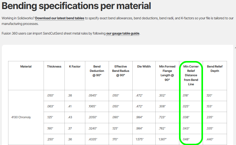
Please note: the Min Corner Relief Distance from Bend Line specification is distinct from our Bend Relief Depth spec.
Learn how to apply the Bend Relief Depth spec in our bend relief requirements writeup!
Checking corner flange clearance with the Min Corner Relief Distance from Bend Line specification
1. Extend the bend lines for each corner flange out past the edge of the flanges.
2. Then, measure the distance between each bend line and the adjacent flange edge.
3. If the distance between the corner flanges’ extended bend line and the other flange’s edge is equal to or greater than the Min Corner Relief Distance from Bend Line specification for your chosen material thickness, the flanges shouldn’t collide.

Pro tip: our Min Corner Relief Distance from Bend Line spec is calculated as follows:
Material Thickness – (Bend Deduction @ 90°/2) + 0.015”
You can find the bend deduction for all of our bendable materials on our Bending Calculator page or in the Material Catalog.
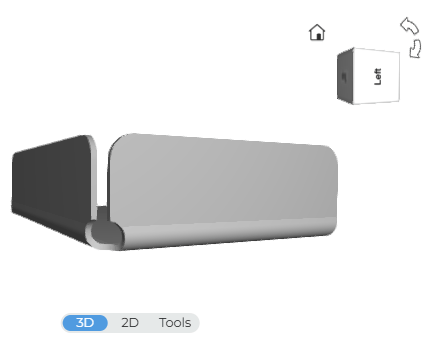
Eyeballing flanges in our 3D bend preview
Our pricing system’s 3D part previewer typically provides a close approximation of how your final part will look. However it should be considered a reference tool – the 3D previewer cannot guarantee that flanges won’t collide.
If you design with adequate clearance as recommended above, you should be good to go!
Got clearance, Clarence?
Avoiding corner flange collision is especially important if you design in a 2D program that doesn’t allow for accurate 3D modeling. Use our guidance here to save draw time and prevent hangups during the production process!
If you’re a 3D CAD user, ensure you set your part up using our bending specifications for the material thickness you plan to use: accurate thickness, bend relief, and K factor. You can find all material bending specifications in our Material Catalog.
For Fusion 360 and SolidWorks users, we provide free sheet metal rules and gauge tables so you can import and design with all the right specs in just a few clicks.
How to Import SendCutSend’s Latest Fusion 360 Sheet Metal Rules
How to Import SendCutSend’s Latest SolidWorks Sheet Metal Gauge Tables
As always, if you have questions about clearance or other design requirements, reach out to our Support team anytime!


