| Adobe Illustrator | .ai |
| AutoCAD | .dxf, .step, .stp |
| CorelDraw | .eps |
| Fusion | .dxf, .step, .stp |
| Inkscape | .eps |
| SolidWorks | .dxf, .step, .stp |
For cutting, we accept 2D vector files in the following formats: DXF (Preferred), AI (Adobe Illustrator), EPS, and DWG.
We also accept 3D files in the STEP and STP formats. If there’s trouble uploading your file, please see our STEP/STP file guide.
If you design your parts in non-CAD software (Adobe Illustrator, Inkscape, CorelDraw) please send us the original (native) .ai or .eps file. We’ll take care of the conversion on our end.
Please note that we cannot accept or process STL (mesh) files or raster-type (JPEG, TIFF, PNG, BMP) files.
We have tutorials to help you convert your art to a vector format in Adobe Illustrator and Inkscape.
The minimum hole or cutout size in waterjet cut parts changes depending on the thickness and type of material.
You can find the minimum hole and minimum bridging/webbing specifications for each material thickness in our material pages. Learn how to find minimum cut requirements for any material.

In the example above the red circles would be too small to cut correctly.
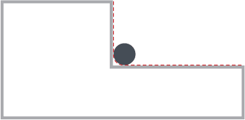
Keep in mind that, similar to the CNC router, all corners will be radiused due to the shape and size of the waterjet stream. The corner radii will be .032”.
Your art should be sent to us at the exact size you want it cut (1:1 scale), in either inch units or mm units. We will not adjust your design based on written dimensions in the drawing, they are ignored by our system. We prefer to work in Imperial Units (inches) when possible, but metric units are acceptable as long as you remain consistent between your file units and the units you input for quoting.
Please note: If your design is in metric units, we only accept mm. We do not support cm or meter units.
Please don’t do this:
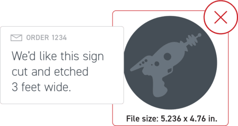
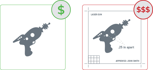
To save time (and possibly money), be sure to remove any instructions, dimensions, notes, borders and unused objects from your file. You should only be sending us the actual cut-path that the waterjet should follow for cutting. Notes, quantities, etc. can be noted on your order, not in the drawing itself.
Please note: “Student Version” lettering is automatically ignored by our systems. No need to worry if you are a student using SolidWorks.
“Open contours” is a fancy way of saying your shape is not connected all the way around. The waterjet will follow the path of your shape. If your shape stops, so does the waterjet.
Viewing your art in Outline or Wireframe mode in your design software is a quick and easy way to find these issues.
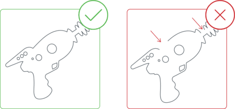
Check your design to make sure no two parts are touching or sharing a line. You also want to be sure that no lines overlap or intersect with each other. The waterjet will not interpret these lines correctly, and the parts will not be cut. To quickly spot these issues, view your part as a wireframe or in outline mode (Illustrator).
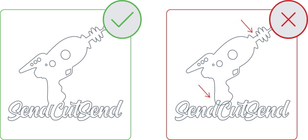
If your vector design has any “active” text boxes, our automated system won’t be able to process the cut properly.
To include text in your waterjet cut parts, convert active text boxes into shapes or outlines, a process that is easy to do in most design software.

Not sure if you have any active text boxes? Hover your cursor over the text, and if it is editable as text, then it needs to be converted into a shape. In Illustrator, this is called “converting to outlines.” In some CAD software, it might be called “explode” or “expand.”
