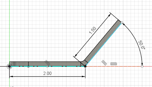
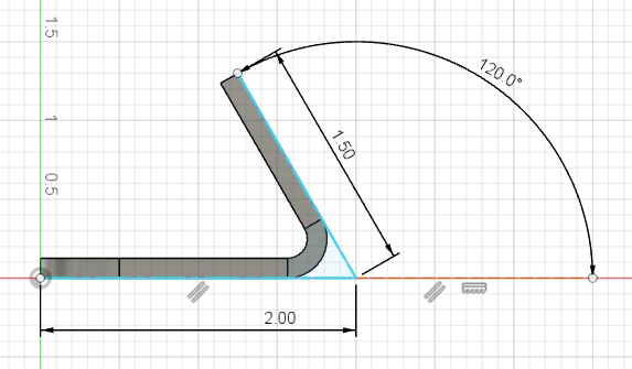
Flange length is measured from the center of a bend to the nearest cut edge. Each material thickness has a minimum flange length specification that must be met in order for us to bend parts. How you measure flange length typically depends on whether you design your parts in a 2D or 3D design software program.
Learn how to find and apply our minimum flange specifications in either case!
Defining the base, flange, and apex
Base, flange, and apex are fundamental bending terms to know before discussing flange length.
Base: the stationary area of your part
Flange: the edge that is bent away from the base
Apex: where the bend occurs (the very center of the bend)
For a deep dive on bending terms, see The Ultimate Guide to Bending Terminology.
Defining flange length
Flange length is the distance from the bend line to the closest cut edge of the part.
The “bend line”, apex, or center of the bend is where the CNC brake’s punch will make contact with the material and form the flange.
A minimum amount of material is required on either side of where the punch will make contact in order to provide support for the bend operation. If there is too little material, the part will deform or even twist during the bending process.
Measuring flange length
Flange length on a 2D flat pattern
If you are measuring flange length on a two dimensional flat pattern, measure from the bend line to the nearest cut edge.
Use our Bending Calculator to make sure that your flat 2D design will result in the final, formed dimensions you want. The flat pattern should account for material stretching that occurs during the bending process.
Flange length on a 3D model
If you create your parts in a 3D modeling design software like Autodesk Fusion or SolidWorks, measure flange length from the apex of the bend.


To ensure that your measurements are accurate, set up your model as a sheet metal part and use our material specifications in your sheet metal rules.
You can find all material specifications for bending in our Bending Calculator Specifications Chart.
We accept STEP and STP format files for quoting, so you can upload them directly to our quoting system. Just make sure your part design file meets our 3D File Guidelines!
Minimum flange length specification
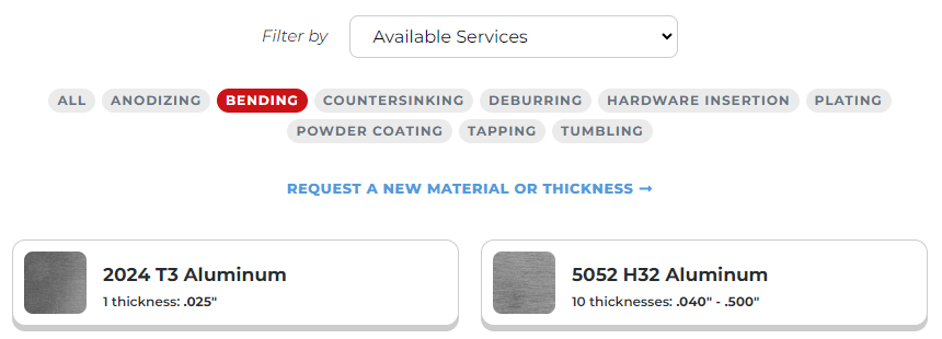
You can find the minimum flange length specification for every material thickness on the individual material pages found in our Material Catalog.
Just select the material you need. You can filter by available services to find it more quickly!

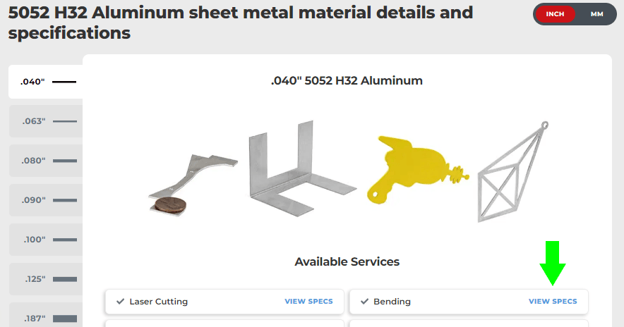
Then click Specifications to jump down to the material details and critical data.

Select the desired thickness and click View Specs to see the bending specifications!

Within the bending specifications, reference the following:
- Min flange length (before bend/flat pattern) 90° or less (obtuse)
- If you’re measuring on a 2D flat pattern, this is the required minimum flat flange length before bending if the bend angle is 90 degrees or less.
- Min flange length (after bend) 90° or less (obtuse)
- If you’re measuring on a 3D model, this is the required minimum formed flange length after bending if the bend angle is 90 degrees or less.
- Minimum length center of bend line 91-130° (acute)
- If you’re measuring on a 2D flat pattern, this is the required minimum flat flange length before bending if the bend angle is 91-130 degrees.
- Since acute angles bend further, they require more flange length to bend successfully.

The thicker the material, the longer the required flange length.
Learn more about minimum flange length and avoiding deformation in our detailed guide: How To Avoid Deformation in Bent Sheet Metal Parts.
Measure twice, upload once!
Meet our minimum flange length requirement for the quickest turnaround on your bent parts. Be sure to review all our bending design guidelines before uploading your part file for an instant quote. If you have questions reach out to our Support team anytime!
