You can prevent deformation and tearing with bent parts by adjusting flange length, moving cut features away from the bend line, or adding bend reliefs. Here’s how!
Adjust flange length to meet the minimum requirement
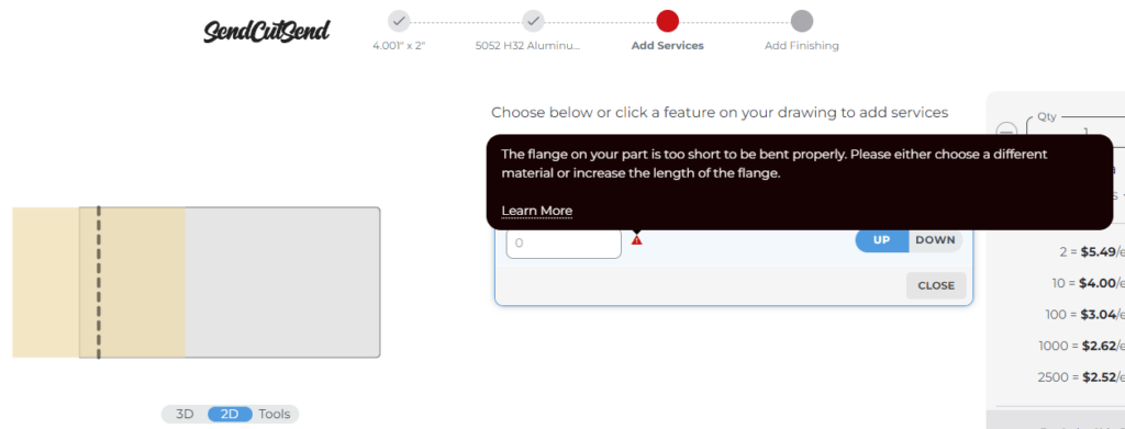
Simply put, if your flange isn’t long enough for the material thickness, we cannot bend it.
Ensure your flange meets the minimum length on both sides of the bend for the whole bend length. This gives the bend even support and prevents deformation or twisting during the bend operation.

Learn how to measure flange length and find minimum flange requirements for each material.
Keep cut features away from the bend
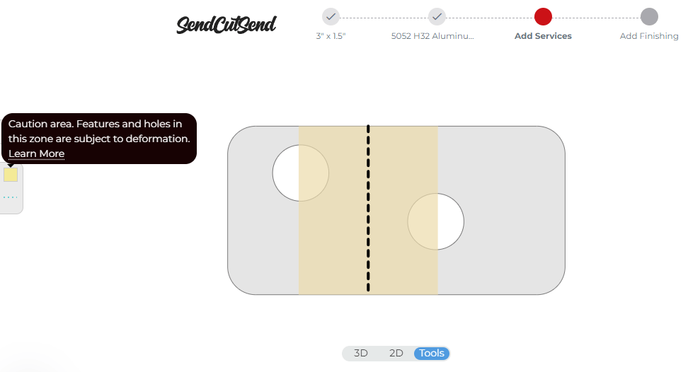
If cut features are too close to the bend, they will deform.
- Confirm the die width that will be used for your material of choice
- This is listed in the bending specifications for the material thickness
- Divide the die width by 2
- Keep cut features at least (die width / 2) away from the bend line or apex (center of the bend)
You can quickly reference the deformation or warning zone in our part preview tools after uploading your design to our website, choosing a material, and adding bending services.

Confirm the die width for all material thicknesses we bend on our Bending Calculator page.
Add bend reliefs or adjust bend location
You can add bend reliefs or move your bend’s location to create more room for the bend to occur.
Here, adjacent bends are too close together and have no relief so the corner will crumple or tear.

Take a look at our detailed Guide to Designing Bend Reliefs for help with creating reliefs for your part.
What if you ignore bend warnings?
You are free to ignore bend warnings when quoting your parts, but keep in mind that we may contact you and request revision if we cannot produce the part as-is.

We typically request design revision in the following cases:
Flange is too short
- For 0.135” material and thinner, approximately 50% of the bend length must meet the minimum flange length.
- For 0.187” and 0.250” thick materials, the entire flange must be the minimum flat flange length on both sides of the bend line in order for us to perform the operation.
- This is because thicker materials are much more likely to “pull” while forming if there isn’t sufficient material on both sides of the bend line for the tooling to make contact with and exert force.
Too many cutouts within the bend caution area
- For material up to 0.135” thick, we’ll request design revision if there are cutouts taking up more than 50% of the bend area.
- For 0.187” material and thicker, a minimum of 85% of the bend length must have solid material that is the minimum flat flange length on both sides of the bend.
Parts that are likely to tear, twist, or pull while being formed
- For example, 0.187” or 0.250” thick material with flanges that have
- Large, asymmetrical cut outs within die lines
- Square cutouts within the bend area that are prone to tearing
- Tapered areas that are less than the minimum flange length required
Polycarbonate parts that do not meet our requirements
- Polycarbonate parts have stricter bending limits than sheet metal parts do.
Here to form, not deform!
Whether deformation affects the form or function of your parts, there are ways to avoid it completely and get great looking parts. Be sure to review our complete bending guidelines before uploading your part file to our website for an instant quote. If you have questions, just ask our Support team!
