SendCutSend does not provide a custom bend radius for any parts since it is set for each material and thickness. Take a look at the material page for your chosen material to find the effective bend radius by thickness, or reference the specifications table at the bottom of our Bending Calculator page.
- Using Autodesk Fusion or SolidWorks? Download our gauge tables to easily apply the right specs.
It’s critical that you use SendCutSend’s specifications or Bending Calculator when setting up your design. Otherwise, your formed part dimensions may not be what you intended. Read on to learn why!
Defining the bend radius
The bend radius specification for each material thickness indicates the expected inside radius of bends after they’re bent to 90 degrees. This provides maximum accuracy for your parts within our bending tolerances.

We list the radius at 90 degrees because 3D CAD programs can use it to calculate the bend allowance and bend deduction for different bend angles once sheet metal rules are set up using our K factor specifications. If you’re designing in a 2D program, we strongly recommend using our Bending Calculator. The Bending Calculator will require you to enter the bend angle for each flange for the same reason.
Please note, we use a process called air bending to form parts. This means we cannot provide curved parts or large radii since we don’t perform roll forming. See our Bending Guidelines to learn more!
Why our bend radii are set
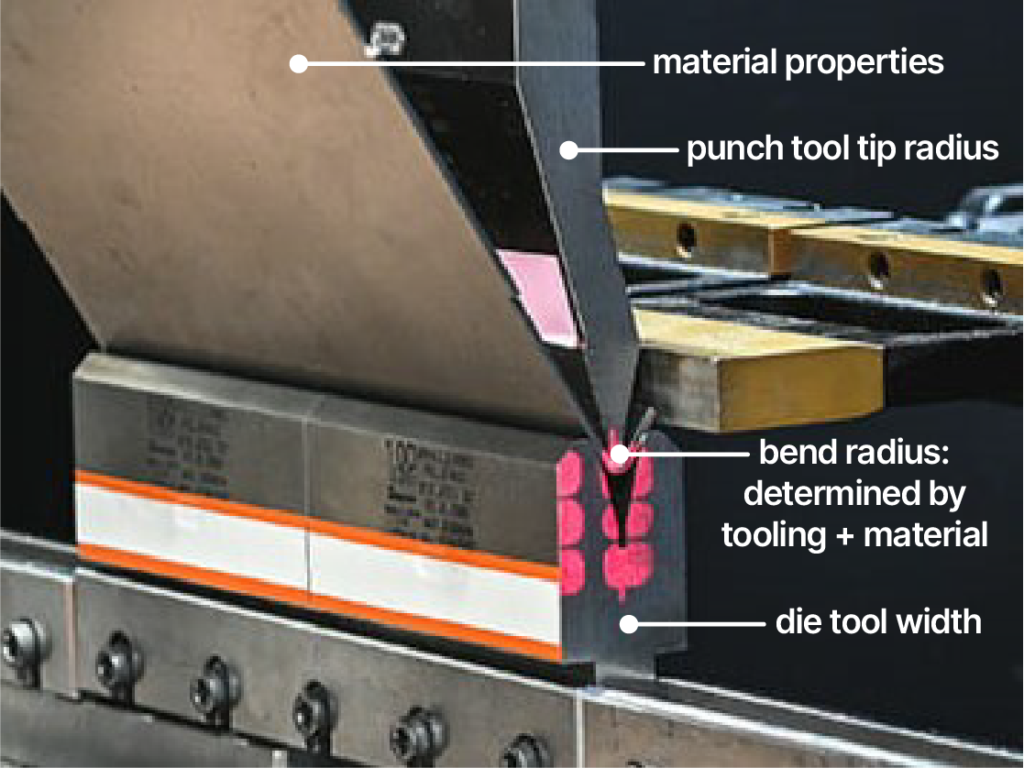
Each material thickness we bend is formed using preset die and punch tooling combinations.
The tooling combination used for a given material thickness, along with the material thickness’s unique properties like tensile strength, determine the bend radius you can expect in that material thickness after the part is bent.
To provide the fastest and most accurate fabrication services possible, we don’t change tooling sizes upon request for individual orders or provide custom radius options.
Sometimes, effective bend radii will not correlate with material thicknesses in a linear fashion. This is due to our tooling combinations along with the material properties; learn more in our writeup on this topic!
The effect of radius on formed part dimensions
Since our bend radii are set for each material thickness, it’s critical that you set up your parts using our specifications. Otherwise, your formed part dimensions are unlikely to turn out the way you designed them.

If you set up your design using a smaller or larger bend radius than we’ll actually provide in the material thickness you order, your formed base and flange lengths will be longer or shorter than intended.
Designing with SendCutSend bending specifications
When designing bent parts in a 2D CAD program like AutoCAD or Adobe Illustrator, use our Bending Calculator to determine the flat dimensions needed in your file to get the final formed dimensions desired.
If modeling bent parts in a 3D CAD program like Autodesk Fusion or SolidWorks, set up your sheet metal rules using our material thickness, bend radius, and K factor specifications. You can find critical bending specifications in our handy chart or the Material Catalog.
For Fusion and SolidWorks users, we’ve made things a little easier! You can download our free gauge tables to apply the right specs with a few clicks.
Bend radius recap
When designing bent parts, remember the following:
- We don’t offer custom bend radii, so design your parts using the listed specification for the material thickness you plan to order.
- Designing with a radius that doesn’t match our specs will result in formed dimensions that don’t match your intended design.
- The effective bend radius for each material thickness is a result of the material properties and punch + die tooling combination used to bend that material.
- Our tooling choices are set for each material so we can deliver bent parts to you faster than anyone else!
If you have questions about our bending guidelines, reach out to our Support team anytime!