To meet our bending requirements, your part must be designed using our material-specific specs, follow our file format rules, meet flange length and bend angle limits, and comply with additional guidelines in our Bending Guidelines.
Our bending and forming requirements make sure your parts form correctly, stay within tolerance, and move smoothly through production. Use this checklist before uploading your file.
Tip: all bending specifications for each sheet material thickness can be found in our Material Catalog.
1. Upload the right file type with bends included
- Accepted formats:
- 2D:
.dxf,.dwg,.ai,.eps - 3D:
.step,.stp
- 2D:
- 2D bend line rules:
.dxf/.dwg: dashed lines for bends.ai/.eps: solid line in a separate color for bends- Bend lines mark the center of each bend

- 3D bend file rules:
- No bend lines needed — just follow our 3D File Guidelines
- Model your part with bends applied in CAD and export as
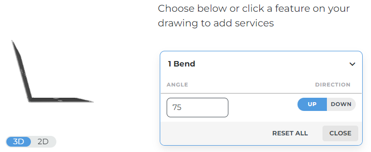
.step - After uploading, confirm bend angles and directions in our system
Why this matters: Proper file setup ensures we know exactly where and how to form each bend, preventing production delays.
2. Confirm material and size limits
- Only certain thicknesses are eligible for bending — check our Material Catalog
- Stay within overall flat size and maximum bend length limits
- Reference our Processing Size Chartfor exact values
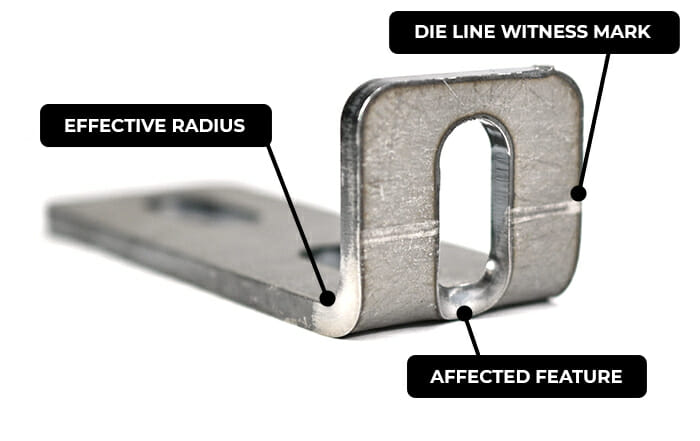
3. Use our bend radius for the material
- Every thickness has a set effective inside bend radius — We do not offer custom bend radii
- Specs are in our bend specification table and Material Catalog
- Bend radius doesn’t always match thickness — see Why bend radius doesn’t always correlate with thickness for details
Pro tip: Fusion 360 and SolidWorks users can import our Autodesk Fusion Gauge Tables or SolidWorks Gauge Tables for instant correct settings.
4. Calculate flat dimensions correctly
- 2D CAD: Use our Bending Calculator to get accurate flat pattern sizes
- 3D CAD: Create sheet metal rules that match our bend radius, K factor, and bend deductions
- SolidWorks: Download our custom bend tables Autodesk Fusion or SolidWork for exact allowances and deductions
- Fusion 360: Import our sheet metal rules from our gauge table guide
5. Meet the minimum flange length
- Each thickness has a minimum flange length requirement listed in the Material Catalog
- See our Flange Requirements Guide for how to measure flanges properly

6. Stay within bend angle limits
- Each thickness has a max bend angle (90°–130°, depending on material)
- Specs are listed in the Material Catalog
- Bend angles are measured from the outside of the bend

7. Follow additional bending guidelines
Depending on your material and design, review these:
- Avoiding Bend Deformation
- If bends aren’t well supported or cut features are too close to bend locations, distortion can occur and impact the success of your part.
- Bend Relief Requirements
- Bend reliefs are highly recommended if adjacent bends meet at a corner.
- Channel Bending Guidelines
- Our channel bending limits depend on whether you’re bending sheet metal or plastic.
- Joggle, Window, and Recessed Bend Requirements
- These types of bends have specific limits.
- Adding Break-Off Tabs to Odd Flanges
- To bend flanges, we need a flat edge on your part that is parallel to the bend location.
- Polycarbonate Bending Guidelines
- Bending sheet plastic comes with a few more limitations than sheet metal
Check it, send it, bend it!
Use this checklist with our full Bending Guidelines before uploading your file. The right prep means your bends will form correctly the first time.
Reach out to our Support team anytime if you have questions!