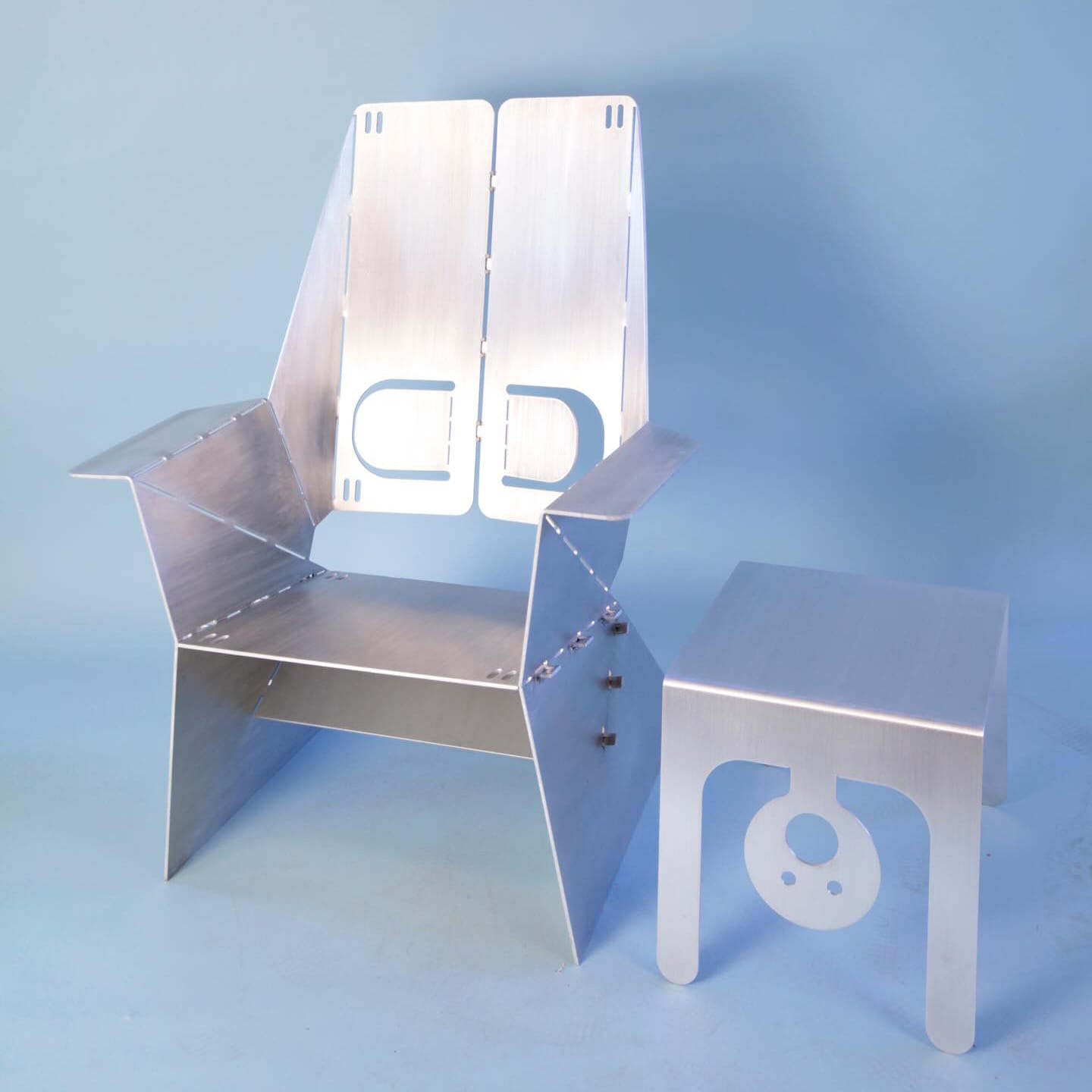
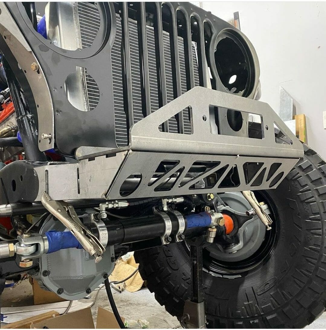
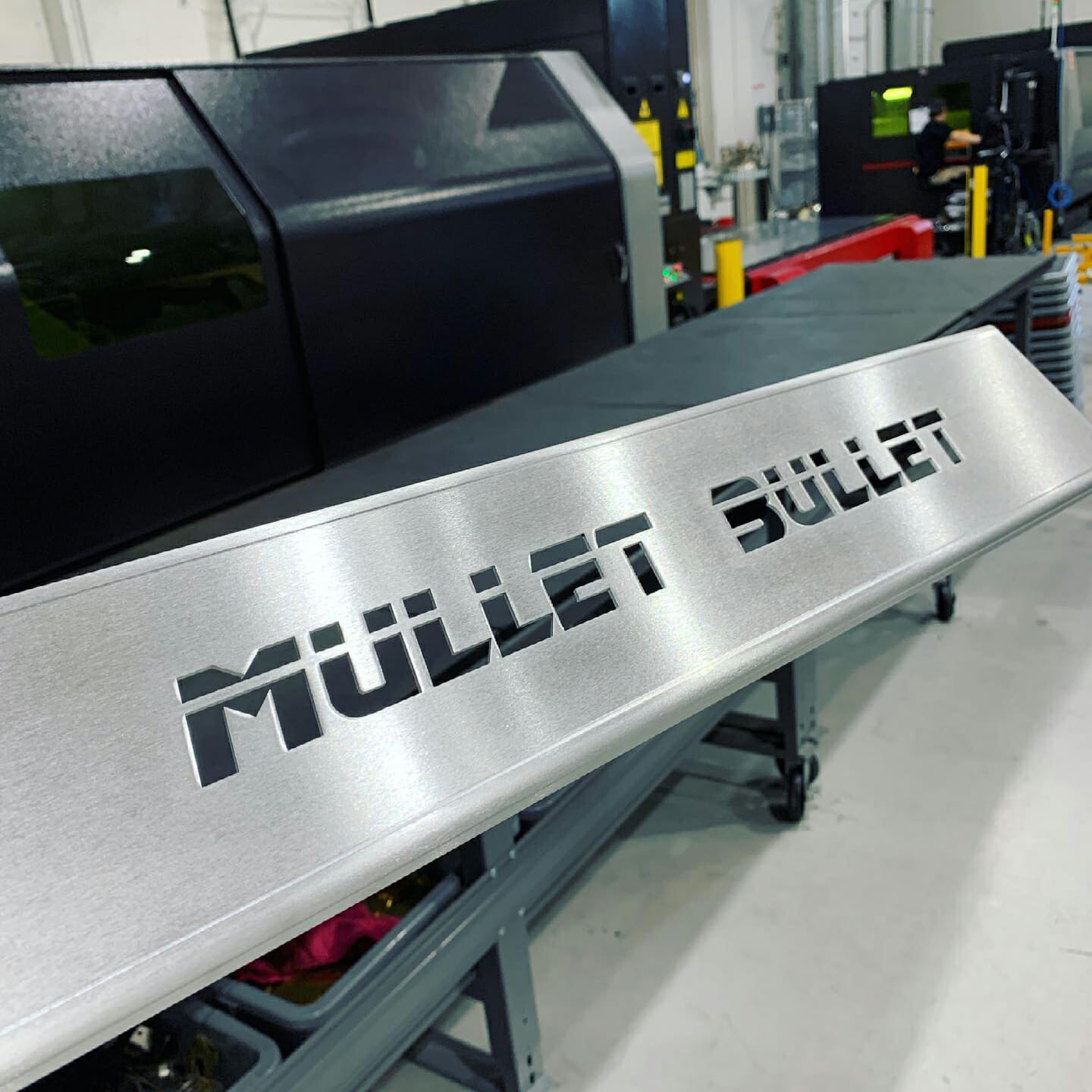
SendCutSend offers plastic and sheet metal bending and fabrication on flat sheet metal and CNC routed parts with no minimum quantity.
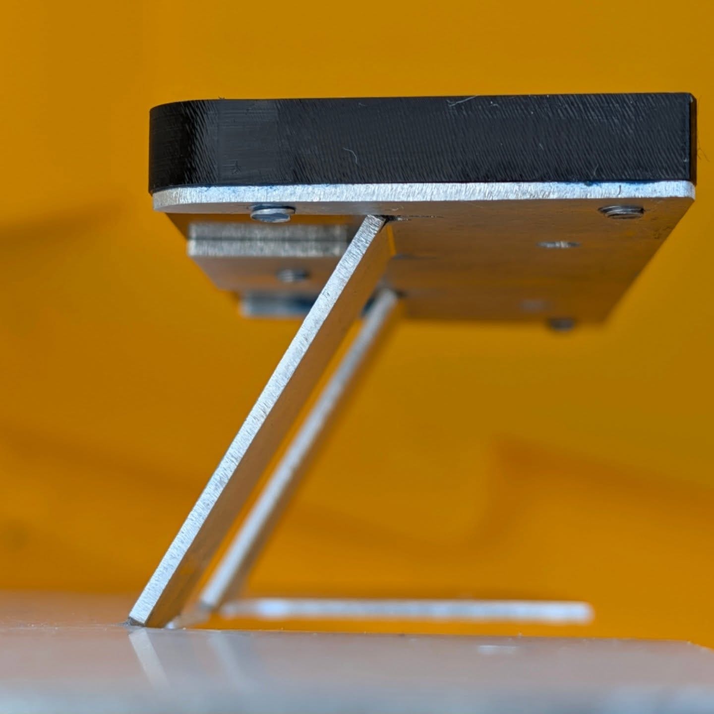
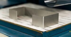
Accurate, repeatable bends
Formed to match your design intent with consistent results across parts and batches.
Fast Turnarounds
Bending is done in-house, adding minimal time to standard production.
Simple, all-in-one workflow
Upload your flat pattern, set your bends, and get instant pricing.
“SCS beats my local shops in every dimension… Did some bends my usual shop would have baulked at.”
Rzad Design
Available materials for Bending
We offer CNC bending for a wide range of materials including aluminum, brass, chromoly, copper, steel, mild steel, polycarbonate and titanium.
For a full list of materials and available thicknesses, please visit our materials page.
One step to a finished part Built to take abuse Looks as good as it performs
Working in CAD? Import our gauge tables for Autodesk Fusion or SolidWorks to apply the latest specifications automatically.
File setup
Upload a 2D vector file (.dxf, .dwg, .ai, .eps) or a 3D file (.step, .stp). You’ll confirm bend angles and flange orientations in a 3D preview during checkout.
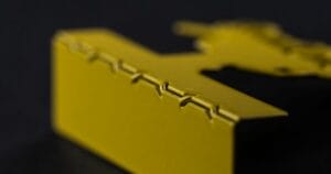
Bend relief notches reduce stress on inner radii and prevent corner tearing or bulging. This is critical for polycarbonate, which cracks without adequate relief.
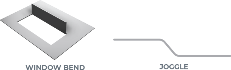
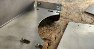
We can bend irregular flange shapes, but we need a flat surface parallel to the bend. Add break-off tabs to create a straight reference edge, then remove them after you receive your part.
We form sheet metal and plastic with air bending, where the punch presses the material into a V-die without bottoming out. This affects bend radii and is especially important to understand for polycarbonate.
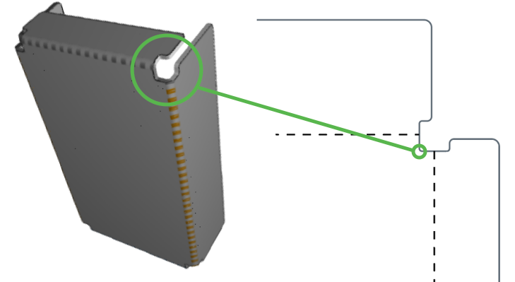
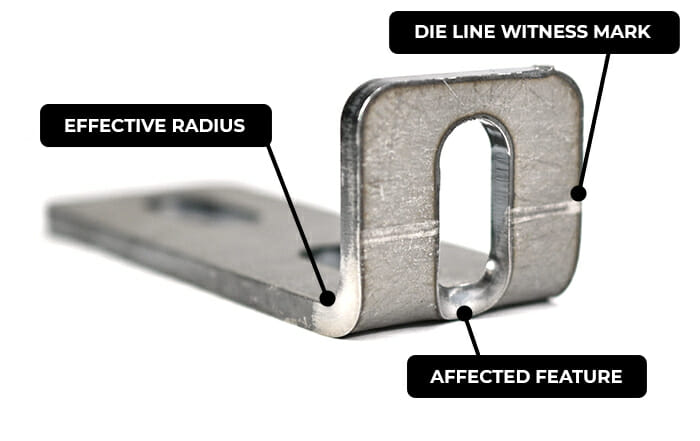
Die lines are witness marks left where the tooling makes contact with your part during forming. Cut features that fall within die lines or the bend area will distort as the material stretches.
Combined lines: Bends on a common axis must be joined. If they’re separate, each will be treated as an individual bend.
Intersecting bends: We can’t bend intersecting lines that don’t have separate flanges.
Incomplete bends: A bend must extend all the way across the area being bent. We can’t form partial bends.
Insufficient contact: Flanges need to meet the minimum flange length for at least ~50–60% of the bend’s length on both sides to provide enough press brake support. Thicker materials (.187″–.250″) need more contact.
Insufficient or missing bend relief: Certain designs require bend relief to avoid damage to the part. Without proper relief, a part cannot be bent accurately. This is critical for polycarbonate parts since the material is prone to cracking.
Additional bending resources
If you’re designing parts for powder coating, these resources may help:
First time I've used Send Cut Send, they exceeded my expectations. I got a fully laser cut part out of 1/2" thick steel for nearly the price of just purchasing the material.
Posted on
Dale Parent
May 4, 2026.
sent cut and sent very fast, nice packaging of the parts. I have a ready recommended to others.
Posted on
Chris Hutchinson
May 4, 2026.
I needed some specific shapes of acrylic cut for Windows for a 3D printing enclosure and even though there was something like 8 or 10 pieces in there, it was under 40 bucks and I think it took something like a week to get to me after ordering. Some of the details are a little fuzzy but I was ecstatic with the result and would 100% recommend.
Posted on
leemach1
May 4, 2026.
Excelent 1st time use of this company. Couldn't believe how easy it was to generate, and how fast the turn-around was! Thanks
Posted on
R L
May 3, 2026.
I'll just say that the team at SendCutSend absolutely came through for me to build additional panels needed after a change order and managed to get them to me in a very tight schedule. Everything arrived perfect! packaged well in protective coverings. Couldn't recommend them enough.
Posted on
Oscar Weir
May 3, 2026.
Awesome service, super quick turn around, and perfect results. Thanks SCS!
Posted on
lee Yates
May 3, 2026.
Awesome service and fast shipping as always. Parts are always spot on from the files we send
Posted on
Conrad Chin
May 3, 2026.
I discovered Send Cut Send when I needed a custom speedometer harness for my motorcycle. The experience from start to finish was seamless. It was easy to upload my CAD file, and I really appreciate the quick and personal responses to my questions. Will use again!
Please note: Pricing examples on our website are provided as general estimates and may not always reflect current prices. While we strive to keep these examples accurate, uploading your file is the best way to see instant current pricing.
Start your first SendCutSend project today!
Upload your CAD design, or try one of our customizable part templates to get instant pricing on your custom laser cut parts. All delivered to your door in a matter of days.