Grade 2 Titanium FAQs and laser cutting design guide
Grade 2 Titanium (commercially pure titanium, or CP-2) is valued for its corrosion resistance, formability, and biocompatibility. Unlike the higher-strength Grade 5 alloy, CP-2 shines when weldability, cold forming, and chemical durability matter most. Below, we cover the most common questions engineers and fabricators ask about Grade 2 Titanium and how to design successfully with it.
Key Takeaways for Grade 2 Titanium
- Excellent corrosion resistance: Performs exceptionally in seawater, chlorides, and oxidizing environments.
- Good strength-to-weight ratio: Lower strength than Grade 5 but still stronger than many non-ferrous metals at less than half the weight of steel.
- Superior formability and weldability: Easier to bend, shape, and join than most titanium alloys.
- Highly biocompatible: Commonly used in medical and dental applications.
- Laser cutting precision: At SendCutSend, CP-2 titanium sheets (.040″) are cut to ±.005″ tolerance with clean, precise edges.
What is Grade 2 Titanium (CP-2)?
Grade 2 Titanium, also called CP-2 (Commercially Pure Titanium, Grade 2), is a non-alloyed titanium known for its balance of strength, corrosion resistance, and ductility. It is one of the most widely used pure titanium grades and often the first choice when applications demand corrosion resistance and weldability rather than extreme strength.
What are the mechanical and physical properties of Grade 2 Titanium?
Grade 2 Titanium has moderate strength with excellent ductility and corrosion resistance. Key properties include:
- Density: 4.51 g/cm³ (about 56% of steel’s weight)
- Tensile strength: ~60 ksi (415 MPa)
- Yield strength: ~50 ksi (345 MPa)
- Elongation at break: ~20%
- Corrosion resistance: Excellent in seawater, chlorides, oxidizing acids
- Service temperature: Up to ~600°F (316°C)
This combination makes it a preferred grade where formability and corrosion resistance matter most.
What industries and applications use Grade 2 Titanium?
Grade 2 Titanium is used across marine, chemical, medical, and aerospace industries where resistance to corrosion is critical. Applications include:
- Heat exchangers, piping, and chemical processing equipment
- Marine hardware, desalination plants, and offshore platforms
- Medical implants, prosthetics, and surgical tools
- Aerospace hydraulic systems, airframe components
- Architectural applications where lightweight corrosion resistance is desired
Explore more material options in our Material Catalog to compare CP-2 titanium with other metals.
How does Grade 2 Titanium compare to other titanium grades?
Compared to Grade 5 (Ti-6Al-4V), Grade 2 has lower strength but greater ductility, weldability, and formability.
- Grade 1: Even softer and more ductile, but less strong.
- Grade 2: The best balance of strength, ductility, and corrosion resistance among CP grades.
- Grade 3 & 4: Higher strength but less formable than Grade 2.
- Grade 5 (Ti-6Al-4V): Far stronger, but less weldable and more difficult to form.
Choose Grade 2 when the part requires shaping, welding, or exposure to corrosive environments rather than maximum load-bearing capacity. SendCutSend stocks both Grade 2 and Grade 5 titanium for your parts
How does Grade 2 Titanium compare to aluminum and stainless steel?
Grade 2 Titanium is stronger than aluminum while being lighter than stainless steel, with better corrosion resistance than both.
- Aluminum: Lighter, easier to machine, but less corrosion-resistant and weaker.
- Stainless steel: Stronger than CP-2 titanium, but nearly twice the weight.
- Grade 2 Titanium: Strikes a balance — lighter than stainless, more corrosion resistant than aluminum, and highly durable in aggressive environments.
For more details, check out our Metal Comparison Guides and article comparing titanium to stainless steel.
Is Grade 2 Titanium biocompatible?
Yes — Grade 2 Titanium is highly biocompatible and widely used in medical and dental applications. Because it does not react with bodily fluids, it integrates well with bone and tissue, making it a trusted material for implants, prosthetics, and surgical tools.
Can Grade 2 Titanium be welded or joined?
Yes, Grade 2 Titanium is one of the easiest titanium grades to weld.
- GTAW (TIG) welding is commonly used with proper inert gas shielding.
- Welded joints retain much of the base material’s strength when contamination is avoided.
- Careful shielding from oxygen and nitrogen is essential to prevent brittle welds.
For parts cut through SendCutSend, many designers pair laser-cut CP-2 titanium with titanium or stainless fasteners for quick assembly.
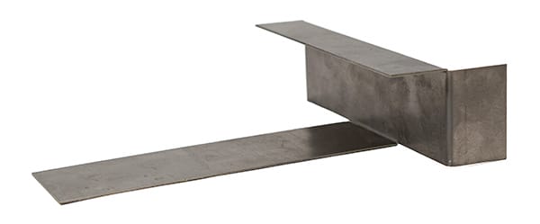
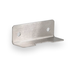
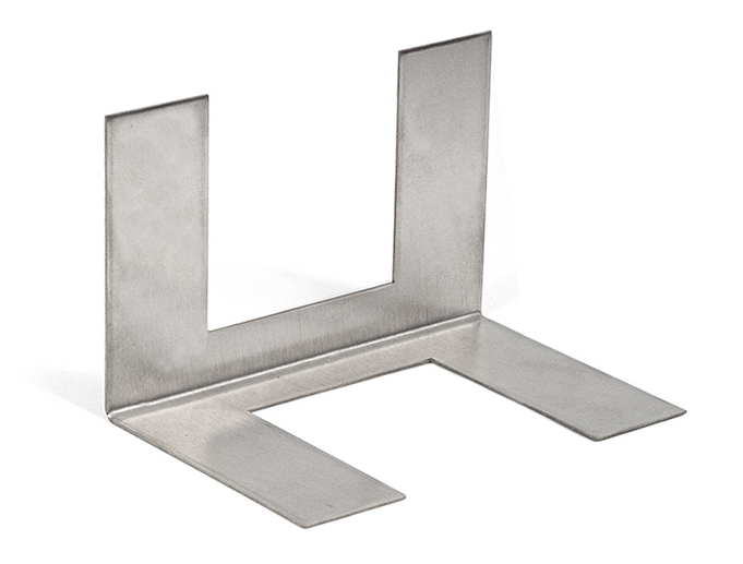
Can Grade 2 Titanium be bent or formed?
Yes — Grade 2 Titanium is highly formable compared to titanium alloys like Grade 5.
- Excellent cold-formability in thin gauges, with less springback than alloys.
- Can be drawn, stamped, or spun into complex shapes.
- Annealing may improve ductility for heavier forming operations.
SendCutSend offers bending on Grade 2 titanium and for best results, follow our bending design guidelines.
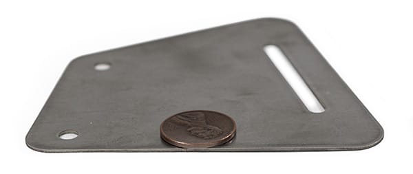
What tolerances and surface finish should be expected with Grade 2 Titanium?
With laser cutting, Grade 2 Titanium achieves tolerances of ±.005″ at SendCutSend.
- Edge quality: Clean, sharp edges with minimal burrs from high-powered laser cutting.
- Surface finish: Ships with a mill finish; light scratches or discoloration from processing may be present.
- Post-processing: Additional finishing options for titanium are limited, so plan designs with as-cut surfaces in mind.
See the Titanium Grade 2 Specifications for feature size and tolerance details. What design tips should be considered for laser cutting Grade 2 Titanium? Optimize your file for titanium’s properties to get the cleanest, most reliable parts.
- Maintain minimum hole sizes and wall thicknesses per our Design Guidelines.
- Use rounded inside corners to reduce stress concentration.
- Allow clearance for assembly where springback may occur after forming.
- Expect slight discoloration at cut edges due to laser processing; plan for this if appearance is critical.
How does Grade 2 Titanium perform in fatigue, corrosion resistance, and durability?
Grade 2 Titanium provides excellent corrosion resistance, long-term durability, and reliable fatigue strength for its class.
- Corrosion resistance: Outstanding in oxidizing environments, seawater, and chlorides.
- Fatigue performance: Not as high as Grade 5 but suitable for low- to medium-stress cyclic loading.
- Durability: Retains integrity in harsh industrial and marine environments over decades.
This makes it the material of choice for chemical plants, marine equipment, and biomedical devices.
Conclusion and design takeaway
Grade 2 Titanium is a top choice when corrosion resistance, weldability, and formability are higher priorities than maximum strength. With SendCutSend’s laser cutting services, you can expect clean, precise edges and tight ±.005″ tolerances in CP-2 titanium parts, delivered in just a few days. Explore our Material Catalog to see how CP-2 titanium compares with other sheet metals for your next project.