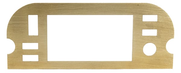

Laser cut, +/- .005" tolerance
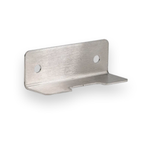
Our laser cut brass is gorgeous, easy to form, bend, and machine. This makes it the perfect material for your smaller hinges, locks, and other fasteners well-suited to brass usage.
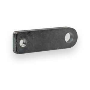
Brass prevents bacterial growth due to its innate antimicrobial properties. It’s great for applications that are exposed to handling, such as bathroom fixtures.
Additionally, unlike steel and iron, brass will not rust when used in external applications, and that makes it great for signage and decorative displays. However, if you intend to use it this way, it’s important to note that it will corrode with moisture, specifically in the form of tarnish.
Brass is a combination of copper and zinc (with a few other trace elements), and the tarnishing effect is similar to copper.
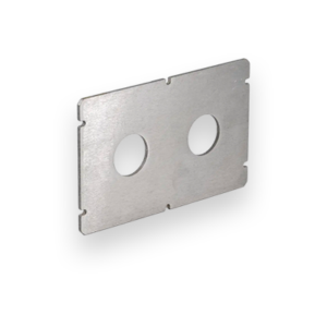
SendCutSend’s brass cutting service will provide beautiful parts made to your specifications.
We guarantee awesome quality parts. If you’re not 100% happy, we’ll give you a refund or remake on the spot – no questions, no hassle.
SendCutSend offers Brass in five thickness options: .040″ (1.02mm), .063″ (1.60mm), .125″ (3.18mm), .187″(4.75mm), .250″ (6.35mm).
When ordering Brass through SendCutSend, there are specific size and thickness parameters to keep in mind. For instant quoting, the smallest part size available is .25″ x .375″, while the largest part supported is 30″ x 44″.
You can add the following services to your Brass parts:
Bending, Deburring, Tapping, and Tumbling
We accept .ai, .dxf, .dwg, .eps, .stp, and .step
Customize one of our simple parts templates

Brass is the alloy designers choose when they need form, function, and finish in one material. Recognized by its golden color and smooth machining characteristics, brass combines corrosion resistance, electrical and thermal conductivity, and easy fabrication — all with a polished, professional appearance. At SendCutSend, we laser cut 260 half-hard cartridge brass sheet to ±.005” tolerance, offering an ideal material for custom components, decorative projects, and electrical applications where precision and aesthetics both matter.
Cartridge brass, or 260 brass, offers the best combination of strength and ductility among standard brass grades. It’s easy to form, polish, and laser cut while maintaining good structural stability.
Fabricators and designers choose brass for its blend of machinability, conductivity, and aesthetic value. It’s one of the few metals that looks finished right off the cutting table, requiring minimal post-processing to achieve a professional look.
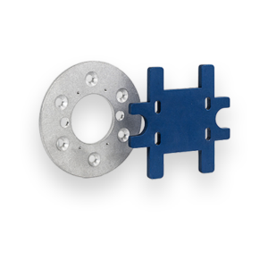
It’s both a functional and visual material — equally at home in control panels, jewelry, or architectural trim.
SendCutSend laser cuts brass to ±.005” tolerance. The material’s reflectivity requires precise calibration, but it cuts cleanly with minimal burr or discoloration.
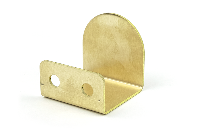
Because 260 brass is ductile and half-hard, it can be:
For specific bend radius guidance for Brass, see SendCutSend’s design guidelines.
Brass’s combination of aesthetics, machinability, and conductivity make it a favorite in both engineering and design projects. Common applications include:
Choose laser-cut brass when your project demands a balance of beauty and function. It’s ideal for parts that will be visible, handled, or require smooth motion and clean conductivity. If your design prioritizes aesthetics, ease of fabrication, or electrical performance, brass is hard to beat. If you need higher strength or outdoor corrosion resistance, stainless steel or 5052 aluminum may be better options. At SendCutSend, we laser cut brass sheets with ±.005” precision, offer 2–4 day lead times, and provide finishing options that let your brass parts shine — literally. Whether you’re fabricating electrical components, signage, or functional prototypes, brass delivers unmatched formability and visual impact.