Laser cut, +/- .005" tolerance

Our C110 half-hard copper is classified as electrolytic copper, which basically means it’s an extremely high purity (greater than 99% copper, ours is 99.9%). For your projects, this means that the material’s electrical properties won’t be hampered by any erroneous leftover elements. You’re getting one of the purest grades available.
Copper, only surpassed by silver in its electrical properties, is perfect for hospital settings due to its antimicrobial nature. In diagnostic equipment, you’ll find this material assisting in transmitting signals for examination and providing the necessary structure in small, vital implants.
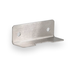
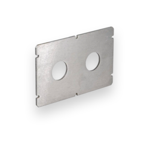
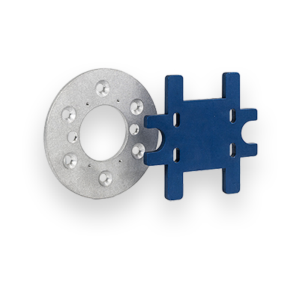
Send us your design and we’ll help you manufacture the highest-quality busbars, heat sinks, connectors and more.
We guarantee awesome quality parts. If you’re not 100% happy, we’ll give you a refund or remake on the spot – no questions, no hassle.
Choose from five thicknesses including .040″(1.02mm), .063″(1.60mm), .125″(3.18mm), .187″(4.75mm), and .250″(6.35mm).
Copper is available at SendCutSend with a range of thicknesses and part sizes. Instant quotes are possible for dimensions between .25″ x .375″ and 30″ x 44″.
You can add the following services to your Copper parts:
Bending, Deburring, Plating, Tapping, and Tumbling
We accept .ai, .dxf, .dwg, .eps, .stp, and .step
Customize one of our simple parts templates

Copper is one of the most recognizable and useful metals in fabrication, prized for its exceptional electrical and thermal conductivity, natural corrosion resistance, and timeless appearance. Whether you’re designing electrical components, decorative parts, or precision mechanical features, copper brings performance and style to the table. Below, we cover the most common questions about copper sheet, its fabrication behavior, and how to get the best results when designing for SendCutSend’s laser cutting services.
Copper is a pure, non-ferrous metal known for its conductivity, corrosion resistance, and easy formability. It’s a mainstay across electrical, decorative, and architectural projects due to its distinct reddish-gold color and resistance to environmental degradation. Copper’s malleability makes it one of the easiest metals to bend and shape, even in thin gauges.
Copper is relatively soft yet strong enough for structural use in many low-stress applications. Typical properties:
This balance of conductivity, ductility, and strength makes copper invaluable for both industrial and artistic applications.
Copper’s versatility spans from high-performance electrical systems to architectural finishes. Common applications include:
For other high-conductivity metals, see our Material Catalog to compare copper with brass or aluminum.
Copper has higher conductivity and a richer natural color, but is softer and heavier than brass or aluminum.
If your design emphasizes conductivity or aesthetic finish, copper is usually the right choice.
Copper laser cuts cleanly with SendCutSend’s high-powered fiber lasers, achieving ±.005″ tolerances and smooth edges.
For best results, avoid ultra-small features below our minimum feature size guidelines.
Laser-cut copper at SendCutSend achieves ±.005″ cutting tolerance with a natural mill finish.
For more details, see the Copper Material Specifications.
Yes, copper is one of the most formable metals available.
SendCutSend offers bending on Copper. To design your copper parts for accurate bends, review our Bending Guidelines.
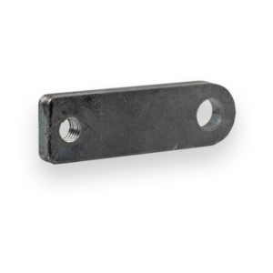
Yes, copper taps and drills very cleanly when designed with proper hole sizing and thread depth.
See our Tapping Guidelines for thread callouts and hole sizing recommendations for tapping your Copper parts.
Copper can be finished for appearance, conductivity, or protection. At SendCutSend, we offer several post-processing options:
See a list of all SendCutSend finishing services for further details and service guidelines.
Copper forms a natural oxide layer, often called a patina, that protects it from corrosion.
If you prefer to maintain a bright finish, a clear lacquer or plating can preserve its color.
Keep copper’s softness and conductivity in mind when designing for laser cutting and fabrication.
For additional fabrication insights, visit our Design Guidelines.
Copper brings unbeatable conductivity, corrosion resistance, and visual warmth to your projects. With SendCutSend’s laser cutting accuracy (±.005″) and available bending, plating, deburring, tapping, and tumbling services, your copper parts can move from concept to finished product with speed and precision. Explore our Material Catalog to see how copper stacks up against brass, aluminum, and stainless steel.