2 Thicknesses
Production Time

Laser cut, +/- .005" tolerance, CNC routed +/- .009"
These tabs hold your parts in place while being cut to ensure the best accuracy possible. Click below to learn what to expect and how to best design with these tabs in mind.
Delrin® 150 is the perfect middle ground between metal and plastic. Our Delrin® 150 is what’s known as an acetal class material. This means that it’s suitable to be used with lubricants and solvents, like gasoline, without any decline in performance. Often used in applications where exposure to wear and extreme moisture is guaranteed, it provides superior strength in areas where metal would be an unwise choice.
You can consider Delrin® the bridge between metal and plastic, offering a host of useful properties that many metals just can’t deliver. A unique fit for robotics, automotive, and in some cases aerospace applications, Delrin carries with it a high creep strength, meaning Delrin® can handle repeated loading without deformation. This makes it a great material for bushings and gears that need to be sturdy enough to withstand impacts, but also lightweight enough to fit project constraints.
In addition to being receptive to fastening applications, our custom cut Delrin® is also especially machinable, making it the go-to thermoplastic for parts that require tight tolerances and more intricate geometry.
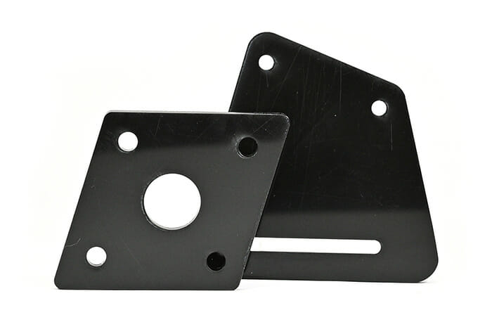
Overall, our custom cut Delrin® parts are positioned for specialized applications that require properties of both plastics and metals to get the job done.
We guarantee awesome quality parts. If you’re not 100% happy, we’ll give you a refund or remake on the spot – no questions, no hassle.
SendCutSend offers Delrin 150 in two thickness options: .125″ (3.18mm), and .270″ (6.9mm).
When ordering Delrin 150 through SendCutSend, there are specific size and thickness parameters to keep in mind. For instant quoting, the smallest part size available is 1″ x 2″, while the largest part supported is 23″ x 44″.
You can add the following services to your Delrin parts:
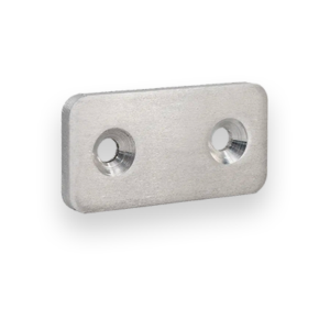
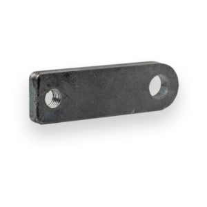
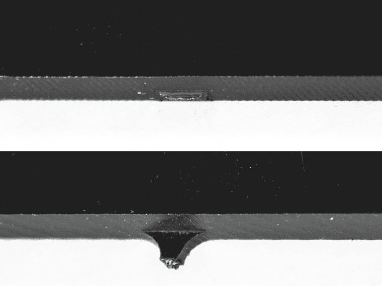
Countersinking and Tapping
We accept .ai, .dxf, .dwg, .eps, .stp, and .step
Customize one of our simple parts templates

Delrin, also known as acetal homopolymer or POM-H, is one of the strongest, stiffest engineering plastics available. It excels in applications where low friction, dimensional stability, and wear resistance matter more than flexibility or impact absorption. Its mechanical behavior is closer to light metal than to traditional plastics, which is why Delrin is used heavily in robotics, aerospace, automotive, and precision mechanical assemblies. At SendCutSend, we route or laser cut USA-sourced Delrin in .125” and .270” thicknesses, depending on material thickness and part geometry, with available countersinking and tapping services. Delrin is ideal for components that need strength, durability, and tight tolerances without the weight or corrosion of metal.
These characteristics make Delrin one of the top choices for mechanical components made from plastic.
Fabricators choose Delrin because it provides metal-like performance without metal-like weight or corrosion. Delrin’s stiffness and low-friction surface make it ideal for precision parts that need to glide, rotate, or withstand repetitive movement. Common reasons fabricators choose Delrin:
Delrin shines where ABS is too soft, acrylic is too brittle, and metal is overkill.
Delrin is significantly stiffer than ABS or HDPE. It maintains shape under load, making it ideal for gears, levers, cams, machine components, and structural plastic parts.
Delrin has a naturally slippery surface, similar to PTFE (Teflon), but with much greater strength. This makes it ideal for:
Parts under repeated cycles — rotating, impacting, sliding — last much longer in Delrin than in most plastics.
Delrin machines like a soft metal:
This is a major advantage over acrylic, which cracks, or over HDPE, which “gums up” during machining.
Delrin absorbs very little moisture and maintains tolerances even in environments with temperature or humidity changes.
Delrin is not recommended for long-term outdoor use. Prolonged sunlight can cause chalking, embrittlement, and surface cracking. For outdoor plastics, consider:
Delrin is difficult to glue, most adhesives do not bond to it. Mechanical fastening is preferred.
While more heat-resistant than ABS, Delrin will still deform or degrade at prolonged temperatures above ~185–200°F.
Like all plastics, Delrin can deform over long periods if subjected to constant, high static load.
SendCutSend chooses the cutting method based on material thickness and part geometry:
Delrin laser cuts extremely cleanly:
Laser cutting gives Delrin that signature polished edge engineers love.
Thicker Delrin (.270″) CNC routes beautifully:
Routing also allows additional services like countersinking and tapping.
Although Delrin cuts well with a laser, parts with extremely sharp internal corners or very thin features may require routing to avoid heat buildup. If your geometry is borderline, the SendCutSend quoting system will automatically choose the safest process.
Delrin is strong and machinable, but designing with intention improves part performance.
More guidance is available in the SendCutSend design guidelines.
SendCutSend currently offers tapping and countersinking for Delrin.
Delrin holds threaded holes extremely well. Tapped holes are ideal for:
Countersinks route cleanly in Delrin with crisp, smooth edges. Perfect for flush-mount screws in:
These services provide ready-to-assemble Delrin parts straight out of the box.
Delrin is widely used anywhere a part needs strength, stiffness, and repeatable mechanical performance. Typical applications include:
If a part needs to slide, rotate, or withstand mechanical load, Delrin is often one of the best plastics for the job.
SendCutSend sources Delrin from domestic U.S. suppliers, ensuring reliable supply, consistent sheet quality, and predictable machining behavior. All cutting, tapping, countersinking, inspection, and shipping take place in our three U.S. manufacturing facilities:
This domestic workflow ensures fast turnaround times, exceptional quality control, and dependable material availability for every order.
Choose Delrin when you need a stiff, strong, low-friction engineering plastic that performs more like a metal than a traditional polymer. It’s one of the best materials for gears, sliders, bushings, and mechanical components that must withstand repetitive movement, wear, and load. You should consider Delrin if your part requires:
At SendCutSend, we laser cut or CNC route USA-sourced Delrin with ±.005” tolerances, offering optional tapping and countersinking for ready-to-assemble components. For mechanical parts that need long service life with low friction, Delrin is one of the strongest choices available.