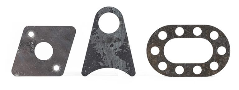

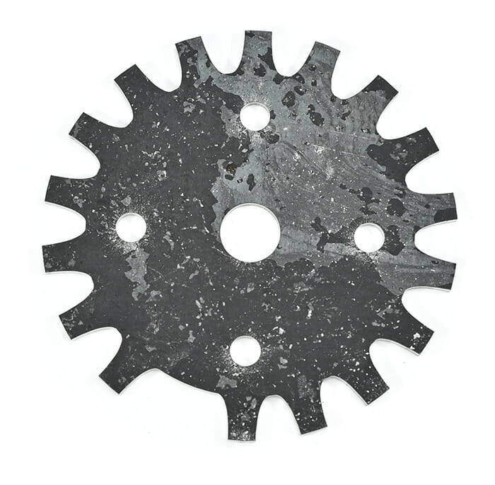
Laser cut, +/- .005" tolerance
Our AR500 steel is similar to AR400 with an even higher hardness, making it more resilient and suitable for applications where extreme abrasion resistance is required. It is built to withstand the same gradual abrasion over extended periods of time, making it well suited for large machinery that endures constant wear. Like its AR counterparts, it also offers outstanding economical value by requiring little maintenance.
High through-hardness is also present in this material, which means that as the wearing action begins to remove some of the surface layer, the quality of abrasion resistance remains constant. Choose AR500 steel when you are laser cutting parts in high impact applications.
We guarantee awesome quality parts. If you’re not 100% happy, we’ll give you a refund or remake on the spot – no questions, no hassle.
SendCutSend offers AR 500 in five thickness options: .119″ (3.02mm), .187″ (4.75mm), .250″ (6.35mm), .375″(9.5mm), .500″ (12.7mm).
AR 500 is available at SendCutSend with a range of thicknesses and part sizes. Instant quoting is possible for dimensions between .25″ x .375″ and 30″ x 44″. For larger projects, custom quotes are available for sizes up to 30″ x 56″.
You can add the following services to your AR500 parts:
Laser Cutting
We accept .ai, .dxf, .dwg, .eps, .stp, and .step
Customize one of our simple parts templates

AR500 belongs to the abrasion-resistant (AR) family of steels. The “AR” stands for Abrasion Resistant, and the “500” refers to its nominal hardness on the Brinell scale (470–530 HBW). To achieve this hardness, the steel is quenched and tempered, giving it the ability to take repeated impact and resist surface wear far better than standard steels.
While mild steels are valued for ductility and ease of forming, AR500 is engineered for durability. It’s the go-to material when parts must survive constant abuse, scraping, or impact — such as in armor, mining chutes, or wear liners.
AR500 is defined by its balance of hardness and strength. Typical values include:
That hardness makes it highly resistant to deformation, but it also limits formability. AR500 is not designed to bend or stretch; it is best used in flat profiles that will see direct wear or impact.
Yes. At SendCutSend, AR500 is cut with industrial fiber lasers, which can handle its hardness with precision.
Because of its toughness, AR500 is not practical to cut with shop tools. Abrasive saws, drills, or hobby-grade cutters wear out quickly and leave inconsistent results.
Like other steels, AR500 develops a small heat-affected zone during cutting. With plasma or torch methods, this zone can be large enough to soften the material at the edges — compromising its wear resistance.
Fiber laser cutting keeps the HAZ narrow, so edge hardness is preserved much better. At SendCutSend, nitrogen assist gas is used to avoid oxidized edges, leaving AR500 parts ready for finishing or use.
For most applications, AR500 is used flat, in its as-cut condition.
AR500 excels anywhere that wear, impact, or abrasion would quickly destroy softer metals. Common uses include:
Its durability makes it indispensable in industries where uptime and reliability are critical.
For most projects, AR500 provides the best combination of availability, toughness, and value.
Yes. Despite its hardness, AR500 is still carbon steel and will rust if exposed to moisture and air. To protect AR500 parts, coatings are recommended:
If corrosion resistance is a priority, a stainless option such as 304 or 316 stainless may be better.
AR500 is more expensive than mild steels (like A36) due to its specialized production, but it is often more affordable than stainless steels when cost is compared per unit of performance.
The real value is in longevity: while A36 may wear out quickly in abrasive use, AR500 can last many times longer, reducing replacement costs.
For instant pricing, upload your design to the SendCutSend quote system.
AR500 is notoriously difficult to machine or cut with shop tools. Saw blades, drill bits, and consumables wear out extremely quickly, and plasma or torch methods often ruin edge hardness.
Outsourcing AR500 cutting to SendCutSend provides:
For most shops and hobbyists, outsourcing saves both time and money compared to fighting with AR500 in-house.
Although AR500 is best left flat and unbent, SendCutSend offers several services to make it safer and easier to use:
These services streamline the fabrication process, especially since AR500 is otherwise very tough on tooling.
AR500 is built for toughness, making it one of the most durable steels you can work with. Its extreme hardness gives it excellent resistance to wear and impact, making it indispensable for armor, targets, and heavy-duty equipment. While it’s too hard for bending or easy machining, laser cutting at SendCutSend unlocks its potential, providing precise, ready-to-use parts with fast turnaround. Add finishing or post-cutting services, and AR500 becomes not just strong, but production-ready.