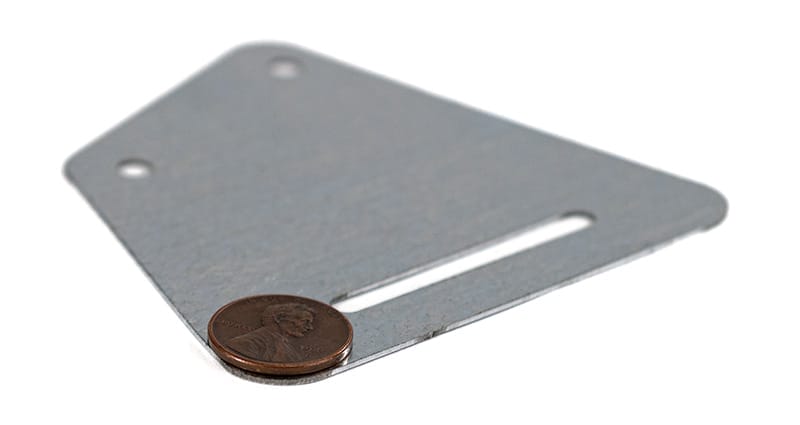
Laser cut G90 galvanized steel offers enhanced corrosion resistance, making it a preferred choice for a wide range of applications, including outdoor and marine environments.
Available in 5 thicknesses from .030"–.074"
Available in black and white
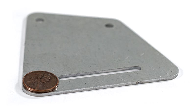
Laser cut sheet metal (+/- .005″ cutting tolerance)
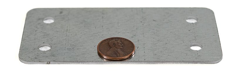
G90 steel, a hot-dip galvanized steel with a coating weight of 90 grams per square meter, offers a myriad of benefits in various industrial applications. Ideal for outdoor applications like construction and automotive components, it combines durability with visual appeal. Its formability and weldability streamline manufacturing processes, while the zinc coating enhances overall strength. The longevity of G90 steel not only ensures durability but also contributes to sustainability by reducing the need for frequent replacements, making it a preferred material for diverse industrial uses.
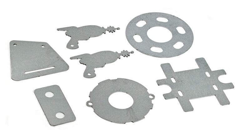
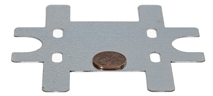
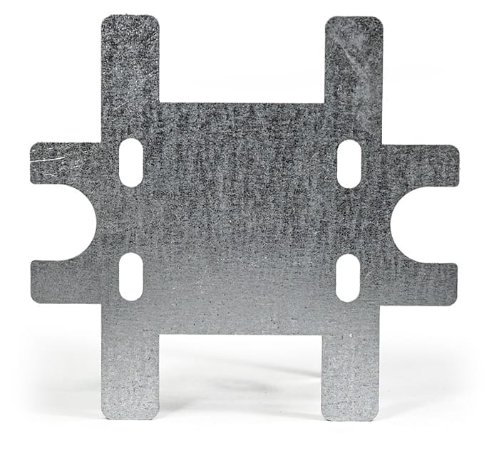
What can you make with G90 Galvanized Steel parts?
G90 steel is a go-to choice for various applications spanning different industries. Since it doesn’t rust easily, it’s an ideal material for outdoor and marine environments.
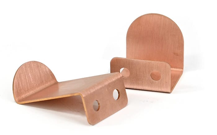
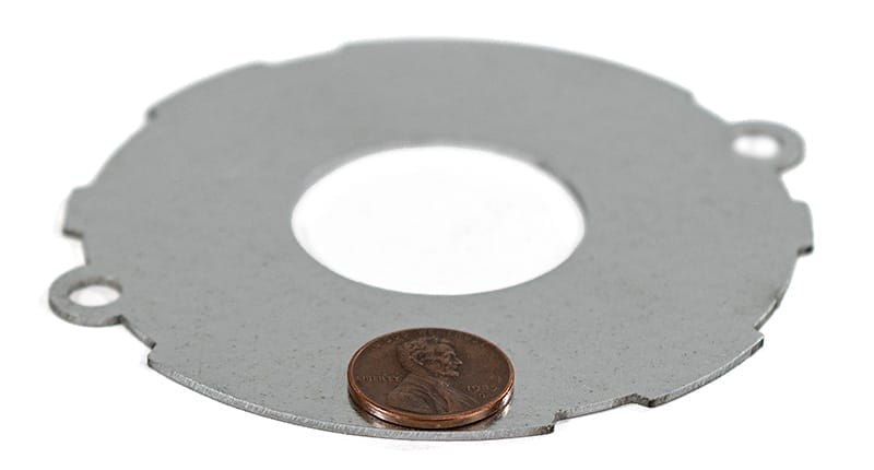
Easy to shape and weld, consider G90 for your next laser cut project. And if you need extra touches, we offer services like bending, putting in hardware, and tapping.
Roofing
Automotive body panels
Structural components
Siding
Agricultural equipment
Marine applications
Chassis components
Highway guardrails
And so much more!
Our laser cut G90 steel sheet metal parts are guaranteed
We guarantee awesome quality parts. If you’re not 100% happy, we’ll give you a refund or remake on the spot – no questions, no hassle.
SendCutSend cuts G90 Galvanized Steel in a broad range of sizes and thicknesses. Instant quoting is available for parts as small as .25″ x .375″ and as large as 30″ x 44″. Larger parts, up to 30″ x 56″, can be ordered through a custom quote.
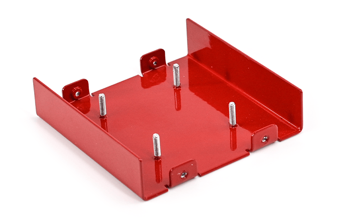
You can add the following services to your G90 Galvanized Steel parts:
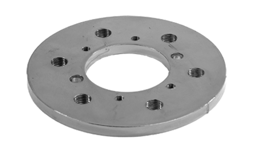
Bending, Dimple Forming, Hardware Insertion, and Tapping
Start your first SendCutSend project today!
Upload your CAD design, or try one of our customizable part templates to get instant pricing on your custom laser cut parts. All delivered to your door in a matter of days.